
Working Principle:
- Projection stage: The projector projects specific structured light (such as light with specific patterns, including discrete light spots, striped light, codes such as Gray code, sinusoidal stripes, etc.) onto the surface of the measured object.
- Imaging stage: The camera captures the structured light image modulated by the object surface (due to factors such as the shape and depth of the object surface causing distortion, deformation, and occlusion of the structured light).
- Calculation stage: Based on mathematical principles and algorithms such as triangulation, the collected images are analyzed and calculated. If the relative positions of the camera and the projector and other parameters are known (usually requiring calibration in advance), the 3D position information of each point on the surface of the measured object can be calculated based on the changes of light in the structured light image, thereby achieving 3D reconstruction.
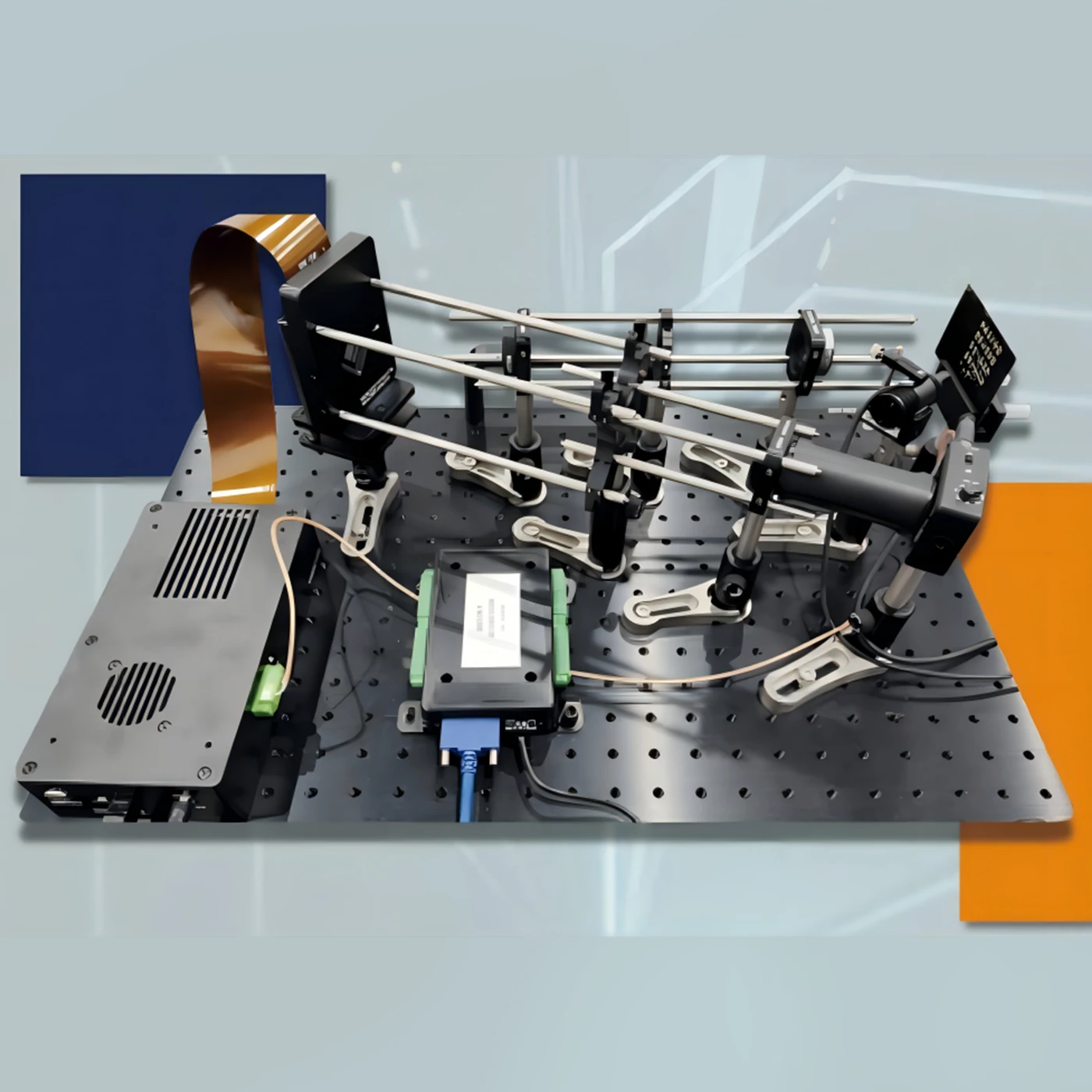
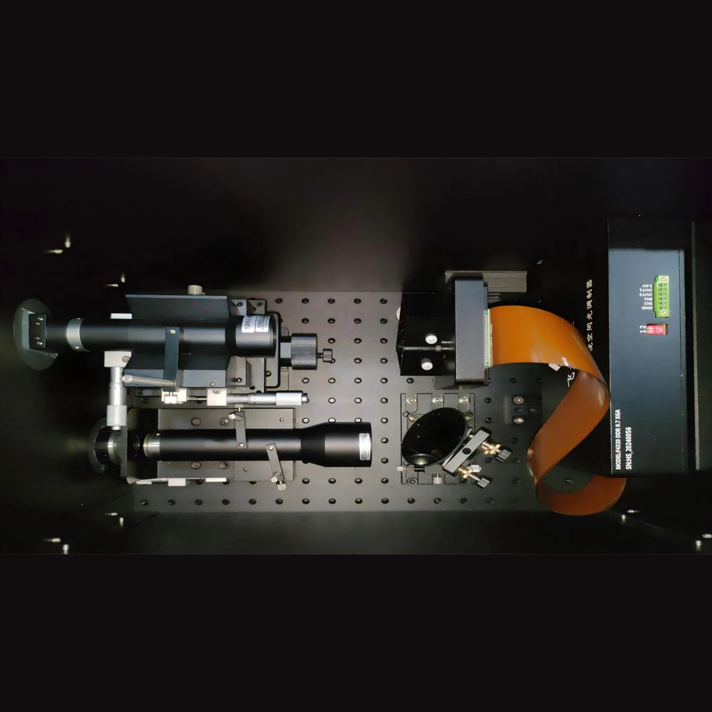
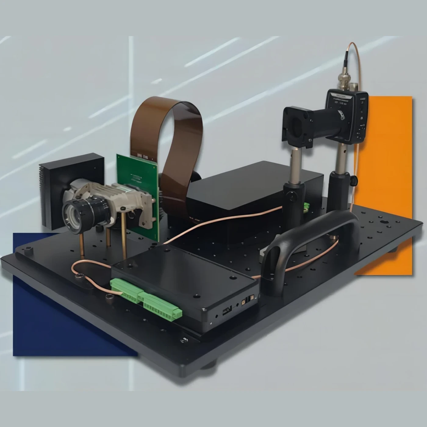
The system is mainly composed of two cameras and a projection module. First, it is necessary to calibrate the imaging models of the two cameras and their relative attitude information. Then, using the multi-frequency phase-shifting structured light coding scheme, the projection module projects coded structured light onto the object surface, and the binocular cameras synchronously capture fringe images. The software algorithm decodes the image sequence to obtain the phase information modulated by the object surface. Based on the phase information and epipolar constraint, the corresponding point matching of the binocular cameras is realized. Finally, the high-precision three-dimensional point cloud reconstruction is achieved by using the binocular stereo vision triangulation principle. The whole process mainly involves the following algorithm technologies: camera calibration, multi-frequency phase-shifting structured light encoding and decoding, corresponding point matching based on binocular epipolar correction, and calculation of three-dimensional coordinates of point clouds.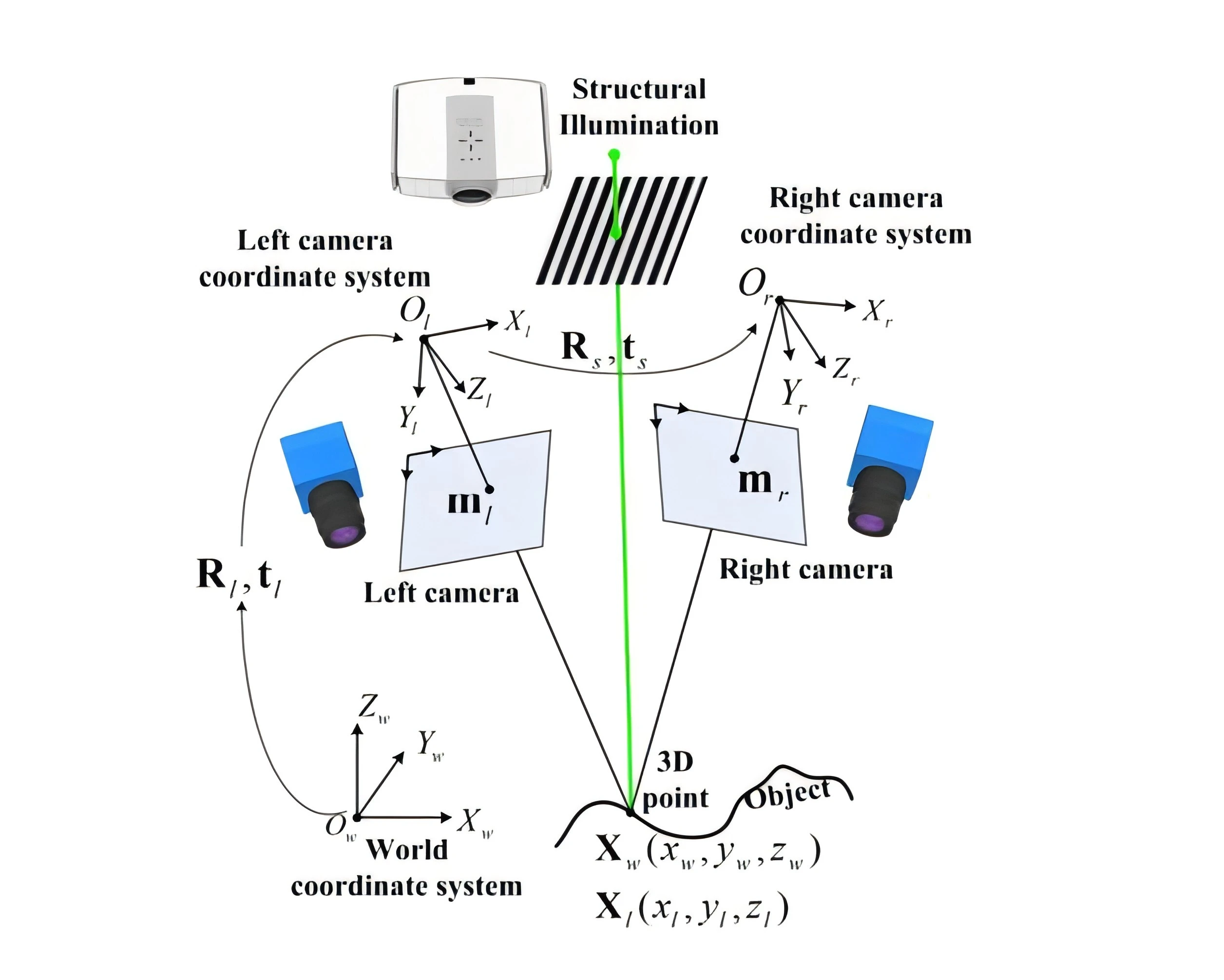
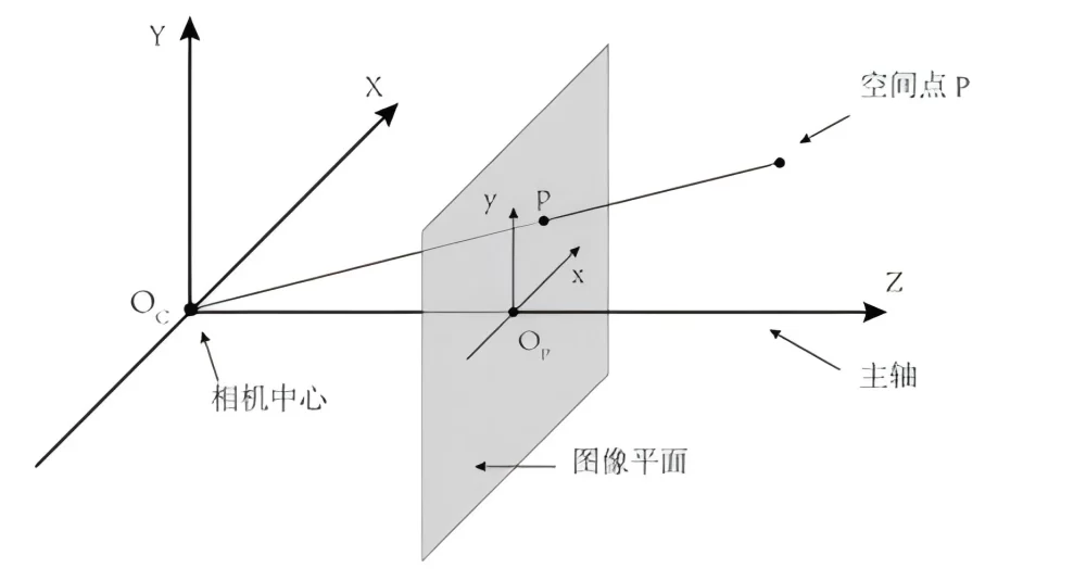
Camera imaging is a mapping from a three-dimensional space scene to a two-dimensional image. The light emitted by an object point in space is converged by the camera lens onto the camera imaging plane to obtain the image point of the object point. This projection process can be characterized by the camera imaging model. Under ideal circumstances, the imaging model of an ordinary pinhole camera can be represented by four camera internal parameters. The following matrix A is the camera internal parameter, which is composed of four coefficients: equivalent focal length ![]() and
and![]() and principal point coordinates
and principal point coordinates![]() and
and![]() .
.


In practical applications, due to the distortion of the camera lens, the influence of distortion on imaging needs to be considered. Therefore, distortion coefficients are introduced into the camera imaging model. Generally, 3 radial distortions and 2-order tangential distortions can meet the accuracy requirements of practical applications.
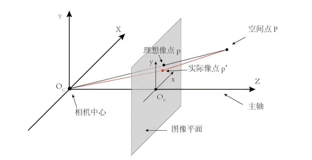
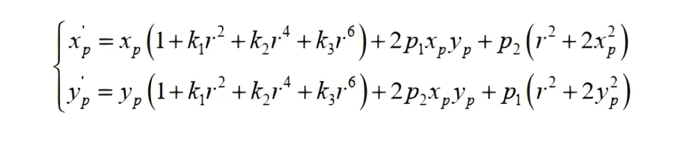
Among them, , and are radial distortion coefficients, and and are tangential distortion coefficients. Therefore, the project uses nine coefficients to characterize the pinhole camera imaging model.
The calibration of the binocular system includes the calibration of the imaging models of the two cameras and the calibration of the relative posture between the two cameras. In the calibration process, only a planar calibration board needs to be placed in front of the system, and the two cameras synchronously capture the images of the planar calibration board. Multiple target postures are captured (to ensure calibration accuracy, it is recommended to have more than 6 postures). The algorithm program detects the corner points of the target image to obtain the sub-pixel coordinates of the corner points and obtain the measured values. The goal of calibration is to adjust the camera imaging model parameters through iterative optimization so that the pixel coordinates of the target corner points projected onto the imaging plane by the internal and external parameters of the camera and the re-projected pixel error of the measured values are minimized. For the binocular system, in fact, the following objective function is optimized:
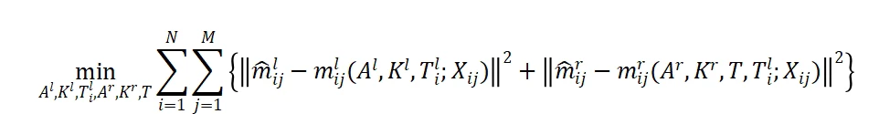
Where ![]() represents the imaging point (measured value) of the jth corner point of the ith target posture on camera l.
represents the imaging point (measured value) of the jth corner point of the ith target posture on camera l. ![]()
represents the pixel point on the camera imaging plane projected by the three-dimensional coordinate ![]() of the jth corner point of the ith target posture through the imaging model. A and K respectively represent the camera internal parameter matrix and the distortion coefficient matrix.
of the jth corner point of the ith target posture through the imaging model. A and K respectively represent the camera internal parameter matrix and the distortion coefficient matrix. ![]() represents the attitude relationship matrix of the ith target coordinate system relative to the left camera coordinate system. T is the attitude relationship matrix between the left and right cameras.
represents the attitude relationship matrix of the ith target coordinate system relative to the left camera coordinate system. T is the attitude relationship matrix between the left and right cameras.

Multi-frequency phase-shifting structured light encoding and decoding In high-precision structured light measurement technology, phase-shifting technology is widely used. Its basic idea is to calculate the phase value containing the three-dimensional information of the measured object surface by collecting multiple frames of fringe images with a certain phase shift. For the N-step phase-shifting method, the nth projected fringe pattern is expressed as:
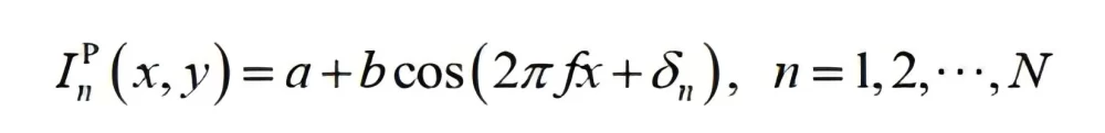
Where ![]() is the intensity of the fringe pattern; a and b represent the background intensity and fringe contrast intensity respectively, f
is the intensity of the fringe pattern; a and b represent the background intensity and fringe contrast intensity respectively, f
represents the fringe spatial frequency. The values of a, b, and f can be set according to measurement requirements. is the phase shift amount. After the camera collects the fringe sequence, the phase modulated by the object surface can be calculated from the image. The phase unwrapping result of N-step phase shift can be expressed as:
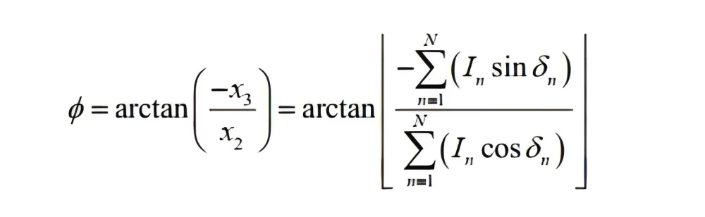
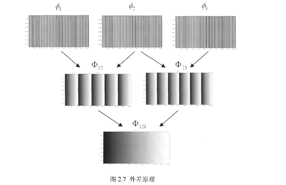
Where![]() is the gray value of the fringe image collected by the camera. The above calculation can obtain the wrapped phase information, and further phase unwrapping is needed. In this project, the three-frequency heterodyne method is used for unwrapping calculation. The basic idea is to project three fringe images with specific spatial frequencies onto the object surface, and then calculate the wrapped phases of the three frequencies. The heterodyne principle refers to that the superposition of two phase functions 𝝋𝟏 (𝒙) and 𝝋𝟐 (𝒙) with different frequencies can obtain a phase function 𝝋3 (𝒙),with a lower frequency. Based on this, the three high-frequency phases can be superimposed into a phase function with a frequency of 1, and then phase unwrapping can be realized. The basic superposition idea is shown in the following figure:
is the gray value of the fringe image collected by the camera. The above calculation can obtain the wrapped phase information, and further phase unwrapping is needed. In this project, the three-frequency heterodyne method is used for unwrapping calculation. The basic idea is to project three fringe images with specific spatial frequencies onto the object surface, and then calculate the wrapped phases of the three frequencies. The heterodyne principle refers to that the superposition of two phase functions 𝝋𝟏 (𝒙) and 𝝋𝟐 (𝒙) with different frequencies can obtain a phase function 𝝋3 (𝒙),with a lower frequency. Based on this, the three high-frequency phases can be superimposed into a phase function with a frequency of 1, and then phase unwrapping can be realized. The basic superposition idea is shown in the following figure:
A key link in binocular three-dimensional reconstruction is the corresponding point matching of the left and right cameras. For a pixel point in the left camera image, in order to find its corresponding point on the right camera, there are the following common technical solutions:
- Use bidirectional orthogonal phases for phase value matching;
- Use unidirectional phase combined with epipolar constraint;
- Perform epipolar correction on the unidirectional phase map and then match the phase value along the horizontal direction.
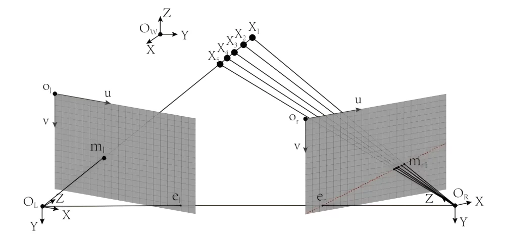
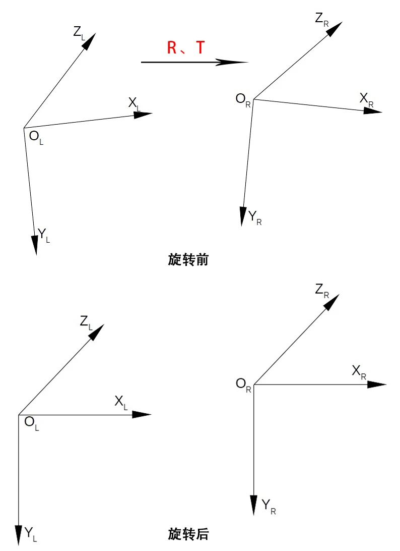
Using epipolar constraint can effectively reduce the computational complexity of finding corresponding points. However, in general, due to the non-parallel main axes of the two cameras, the epipolar line is an inclined straight line. If lens distortion is considered, the epipolar line will become a curve. Looking for corresponding points on a curve still has a relatively large computational complexity. Epipolar correction can correct the main axes of the cameras of the two images to a parallel state and eliminate the influence of vertical parallax and distortion, so that the corresponding points are always located on the same horizontal line. This will further simplify the calculation process of finding corresponding points. Therefore, in this project, the epipolar correction scheme, that is, scheme 3, is used.
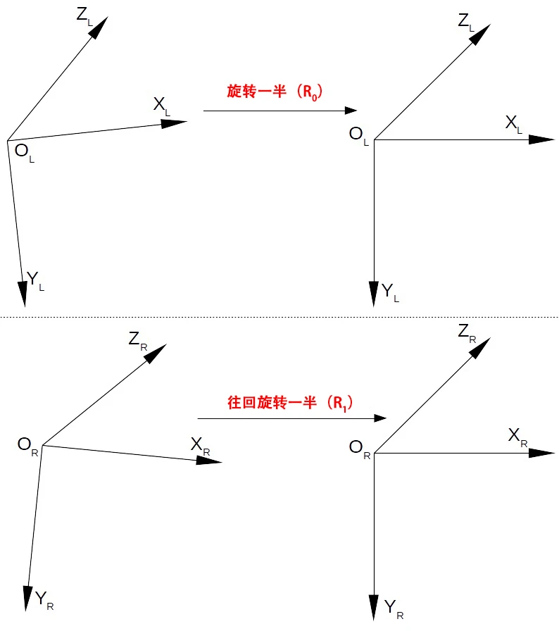
This project will use the Bouguet algorithm to achieve binocular epipolar correction. In principle, the algorithm processing process mainly includes the following three steps:
Step 1:
According to the binocular pose information R and t, each of the two camera coordinate systems is rotated by half so that the coordinate axes of the two coordinate systems are parallel. As shown in the following figure:
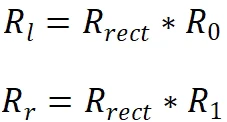
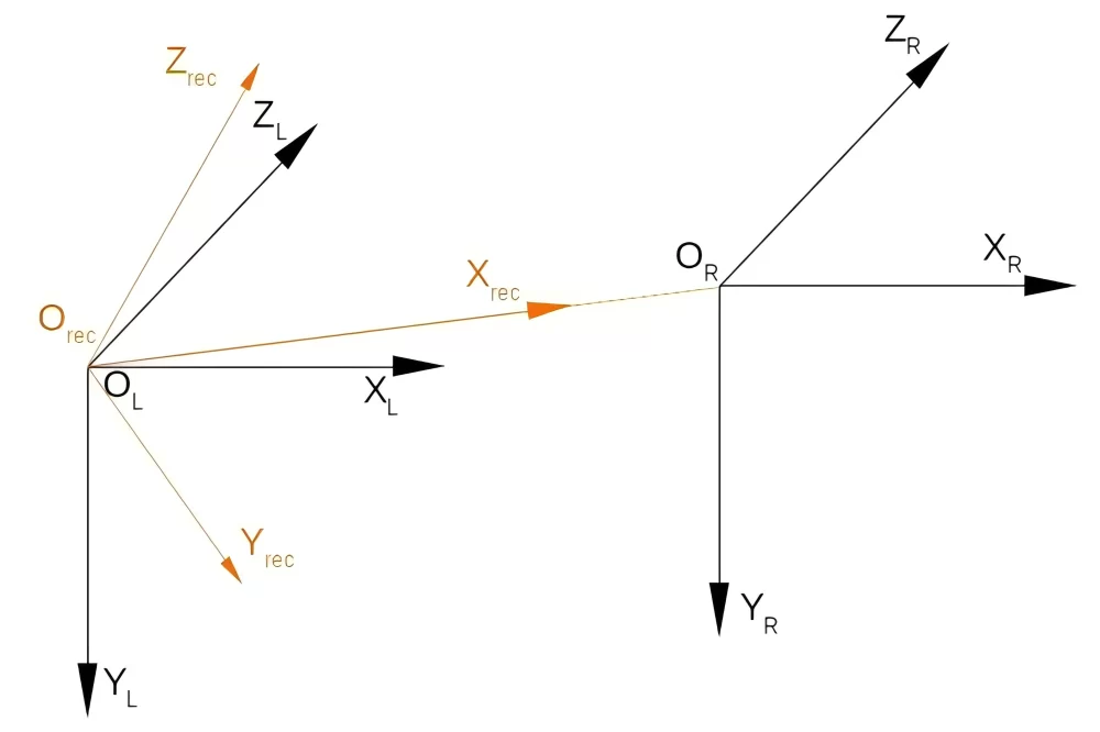
Step 2:
Establish a reference coordinate system and rotate the two coordinate systems to be coplanar, as shown in the following figure. The three coordinate axes of the coordinate system are defined as follows:
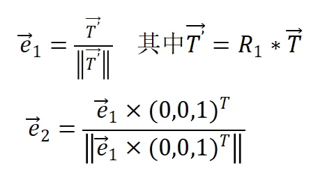

Based on the above definition of coordinate axes, the matrix to be rotated can be obtained:
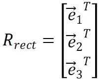
Therefore, during the entire epipolar correction process, the two camera coordinate systems are rotated as follows:
Step 3:
Construct a virtual camera and establish the pixel mapping relationship between the pre- and post-correction images.
In addition, in practical engineering, the measurement depth range can be limited, so that the search range of corresponding points becomes a straight line segment, further narrowing the search range of corresponding points. Since the phase map is composed of discrete pixels, after finding the whole-pixel corresponding points by comparing the phase values, in order to further improve the accuracy and combined with the characteristic of linear phase change, this project uses a linear interpolation algorithm to calculate the sub-pixel corresponding points.
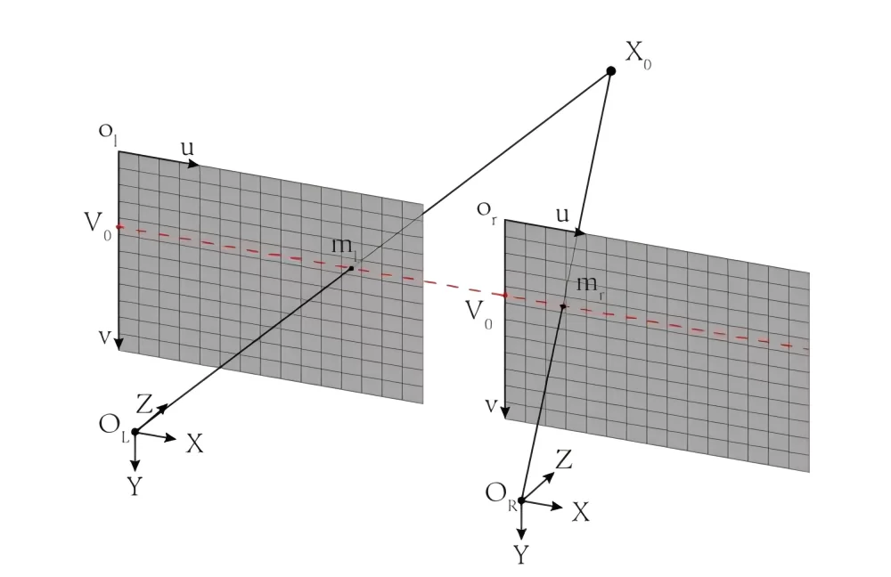
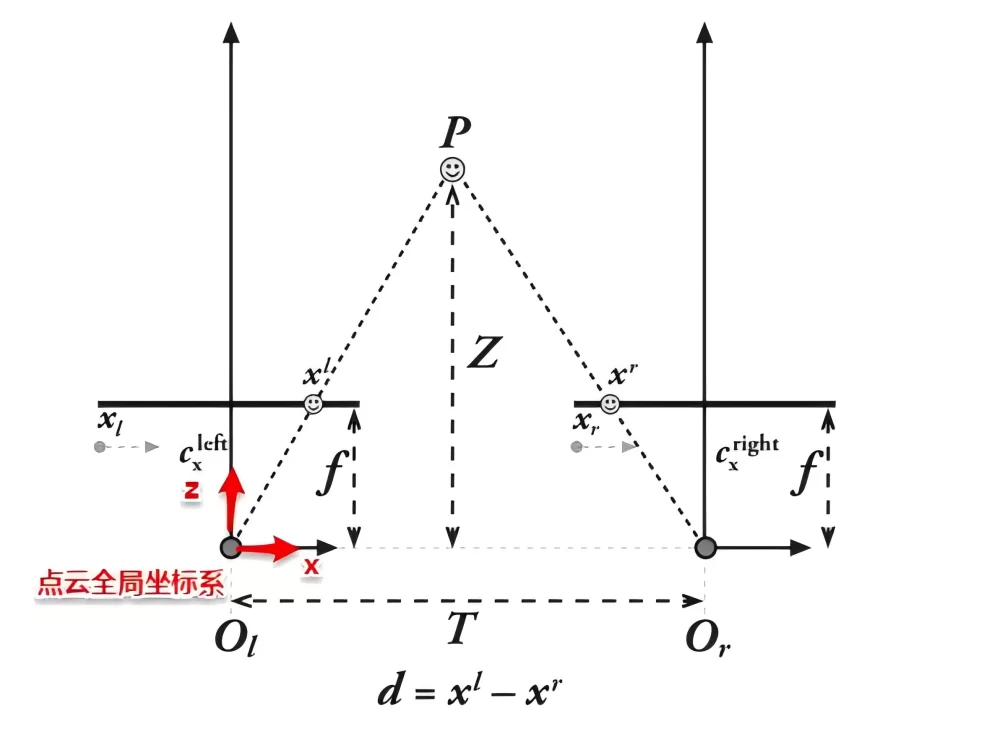
- After completing the corresponding point matching, the disparity map is obtained. In order to convert the disparity map into a three-dimensional point cloud, further calculations are needed. After epipolar correction, the geometric structure of the binocular camera is as shown in the following figure. According to the principle of triangle similarity, we can obtain:

Since in engineering applications, the disparity ![]() is directly obtained by subtracting the horizontal pixel coordinates of the left and right camera images. The origin of its coordinate system is defined at the upper left corner of the image. So the above formula can be converted to:
is directly obtained by subtracting the horizontal pixel coordinates of the left and right camera images. The origin of its coordinate system is defined at the upper left corner of the image. So the above formula can be converted to:
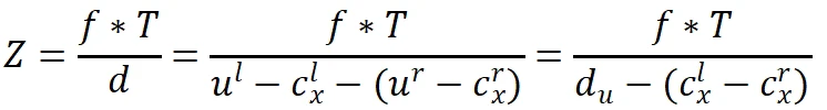
Also according to the principle of triangle similarity:
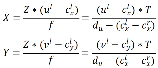
Where,  is the principal point coordinate of the left camera coordinate system after epipolar correction,
  is the pixel coordinate of the left camera image after epipolar correction, f is the focal length of the virtual camera after epipolar correction, and T represents the baseline length of the two camera coordinate systems after epipolar correction. For the left-right binocular system, it is equivalent to the length along the x-axis direction.
The software is developed in C++ language and uses Qt to develop the UI interface. The software mainly includes the following functions:
- Realize synchronous trigger acquisition control of projection and camera;
- Realize the calibration algorithm of the structured light system;
- Realize the multi-frequency structured light decoding algorithm;
- Realize binocular stereo matching with epipolar correction and reconstruct single-point cloud data (without multi-view registration and point cloud fusion);
- Point cloud rendering and display;
As mentioned above, the software realizes the functions of hardware acquisition control, system calibration, and single-point cloud scanning and reconstruction of the entire system.
| Categories | Specification and Model | Unit | Quantity |
| Projection module | Resolution not less than 720p, projection ratio about 1.2:1, light source: RGB three-color LED | set | 1 |
| Calibration board | 12*9 glass substrate checkerboard calibration board (accuracy not less than 0.01mm) | piece | 1 |
| Area array camera | 5 million pixels (including USB cable and trigger cable) | piece | 2 |
| Lens | Focal length 12mm | piece | 2 |
| Bracket | Tripod, base screw, support plate, universal pan-tilt, adapter base plate | set | 1 |
| Light-shielding cloth | 2*2M black flocking light-absorbing cloth | piece | 1 |
1.Compared with some other 3D imaging technologies (such as purely passive binocular stereo vision), it is an active 3D measurement method.
2.It can achieve 3D imaging and measurement of objects to a certain extent relatively well, especially having wide applications in scenarios such as industrial inspection (such as object volume and external dimension measurement, etc.), biometric recognition (such as 3D face recognition, etc.), and robot vision navigation (utilizing 3D environmental information).