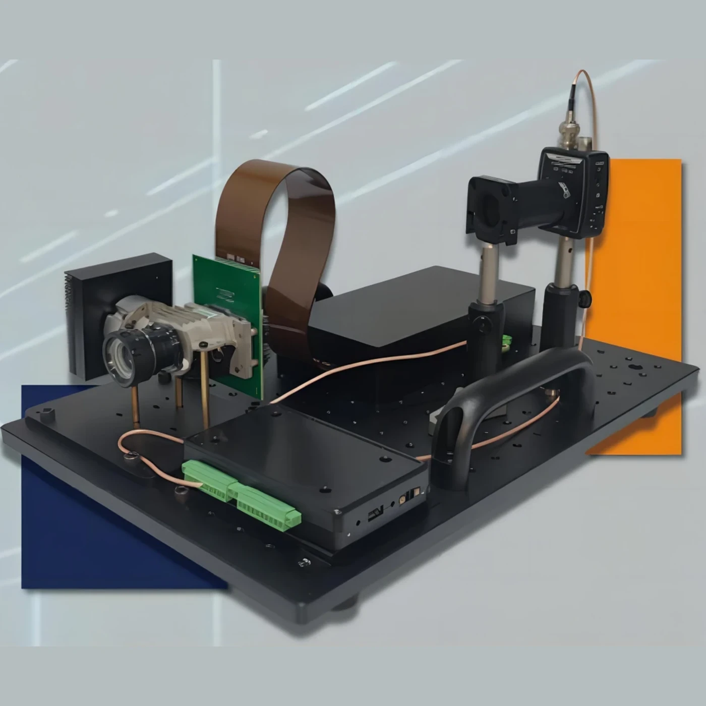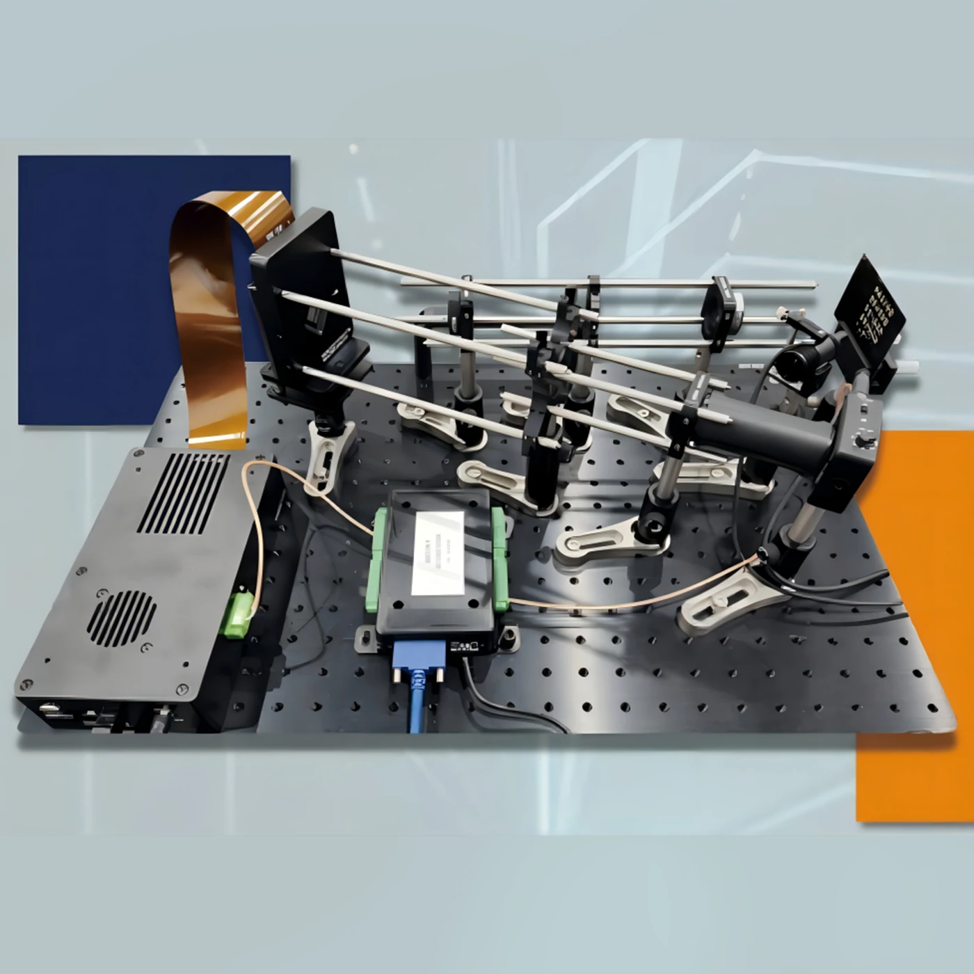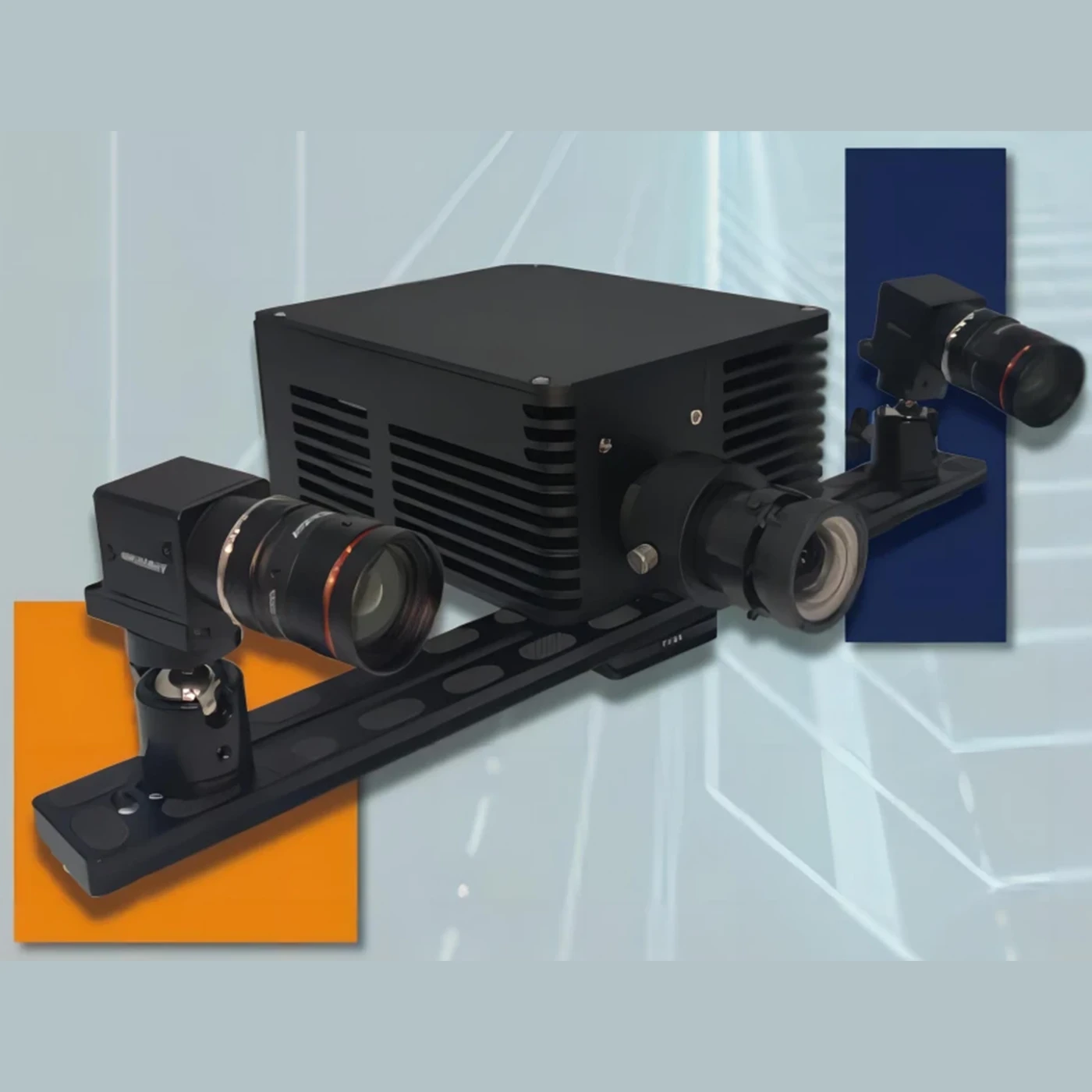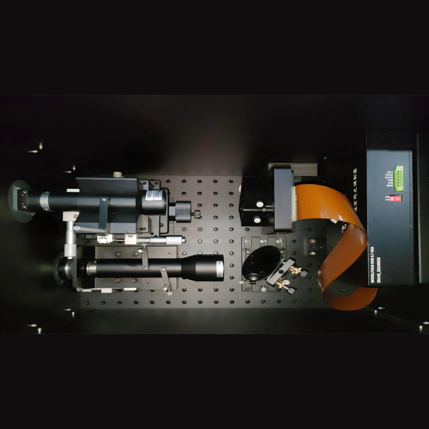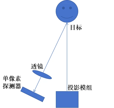
An active visible light single-pixel imaging system illuminates the target scene by emitting visible light from the active light source in the system. Then, the spatial light modulator modulates this beam of visible light to generate a series of specific light field patterns (such as stripes in different directions, specific patterns, etc.). The modulated light irradiates the target scene, and the target scene reflects or transmits this light. At this time, there is only a single-pixel photodetector to receive these light signals after being acted on by the target scene.
Under different light field patterns’ irradiation, the single-pixel detector will collect a corresponding series of light intensity information.
Finally, through specific algorithms, such as the compressive sensing algorithm, etc., the collected light intensity data under these different patterns are processed and calculated to reconstruct the two-dimensional image of the target scene.
The system is mainly composed of a projection module, a lens (with a focal length of f), and a single-pixel detector. Among them, the projection module is composed of a light source, a beam splitter (BS), a digital micromirror array (DMD), and a lens. The design scheme of the active single-pixel imaging system is shown in Figure 1.
- Calibrate the relative distance between the projection module and the target, and project the coding clearly onto the target to be measured.
- Calculate the ratio of the width of the projected image (x1) to the width of the detection surface of the single-pixel detector (x2).
- Realize the optical conjugate between the DMD and the single-pixel detector through single-lens imaging. Suppose the distance from the single lens to the DMD is L1 and the distance from the single lens to the detector is L2. L1 and L2 satisfy the single-lens imaging formula:
 , and at the same time should satisfy
  ,The center of the DMD, the center of the lens and the center of the single-pixel detector should be collinear. Among them, the single-pixel detector transmits the detection result to the computer through the acquisition card.
 - The system realizes single-pixel imaging of a single target through multiple encodings and single-pixel acquisitions. The number of encodings and the number of acquisitions are about 10% of the number of coding pixels. The software algorithm obtains the target image by decoding the light intensity sequence collected by the single-pixel detector according to the coded image. The whole process mainly involves the following algorithms and technologies: GAP-TV algorithm, projection calibration, random coding of illumination light, etc.
Single-pixel imaging compresses the two-dimensional spatial scene after encoding to the overall intensity value collected by the detector. The encoding is realized by the active illumination provided by the projection module. This projection process can be described as the Hadamard product of the two-dimensional scene and the encoding. Under ideal conditions, the active illumination coding of the two-dimensional scene by the projection module can be represented by the following mathematical process:
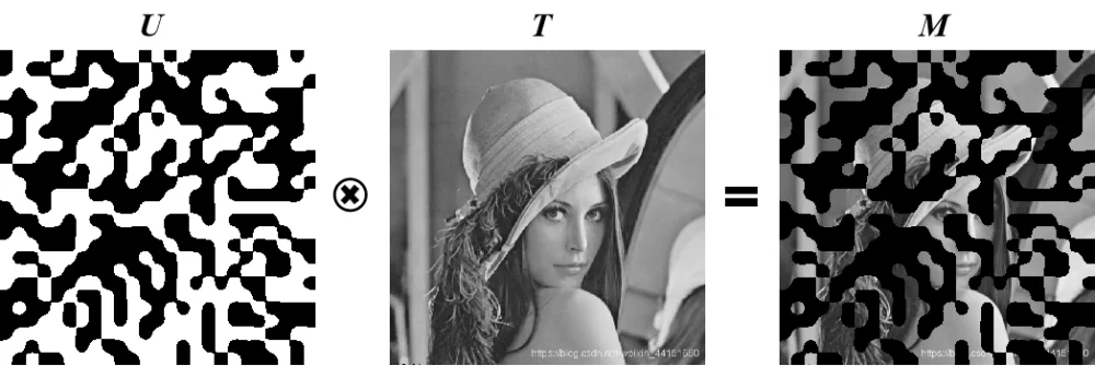
Among them, U is a random binary encoding, which is projected onto the two-dimensional scene T through the projection module, and the coded scene M is obtained by superposition. The projection module projects the encoding onto the two-dimensional scene through the lens. The projection distance is adjusted by rotating the lens. When the coded image is clearly observed with the naked eye, the calibration is completed.
The coding process of illumination light is integrated in the projection module. The projection module is composed of a parallel light source, a TIR prism and a digital micromirror array (DMD). The parallel light is irradiated to the DMD through the TIR prism. The incident angle is 24 degrees with respect to the vertical direction of the DMD surface. The coded image is loaded on the DMD. The light-transmitting part in the coding is reflected perpendicular to the surface of the DMD and imaged to the two-dimensional scene through the lens. The light-shielding part leaves the optical path through the TIR prism.
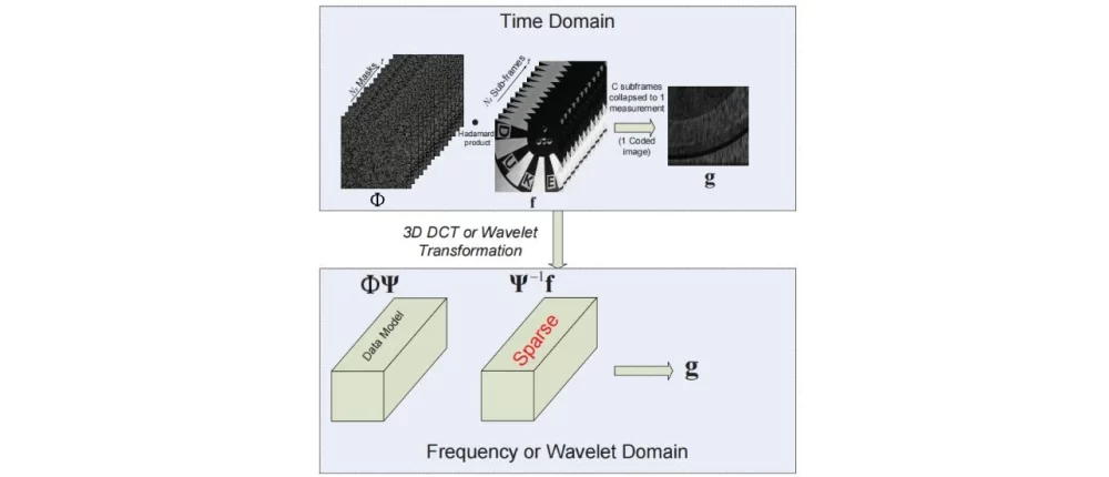
The Generalized Alternating Projection (GAP) algorithm is a general reconstruction algorithm. GAP utilizes the Euclidean projections on two convex sets to enhance the data fidelity and the sparsity of the structure respectively. It does not require prior knowledge of the target scene and can effectively scale the size and compression ratio of the delayed image. In addition, as the algorithm proceeds, the results produced by the GAP algorithm monotonically converge to the true value. Monotonicity is generally observed in a wide range of experiments and is theoretically established under a set of sufficient conditions of the forward model. The reconstructed sub-frames are continuously improved in successive iterations. The user can stop the calculation at any time to obtain intermediate results, and the user can resume the calculation to continue improving the reconstruction. Figure 2 illustrates the basic principle of the GAP algorithm.
The following are the main steps of the GAP algorithm:
- Data fidelity is guaranteed by projecting
 onto a linear manifold composed of all eligible high-speed frames. This can be integrated into the observed snapshot g according to the forward model
  集成到观测的快照g中。
In other words,![]() is the solution set of an undetermined linear equation system, which can be disambiguated by utilizing the structural sparsity of f in the transform domain.
is the solution set of an undetermined linear equation system, which can be disambiguated by utilizing the structural sparsity of f in the transform domain.
- weighted value

Let![]() ,
,![]() and
and ![]() be orthogonal transformation matrices along two spatial coordinates and a time coordinate respectively. The frame f is represented in
be orthogonal transformation matrices along two spatial coordinates and a time coordinate respectively. The frame f is represented in ![]() as:
as:
![]()
The transform coefficients![]() are partitioned into m disjoint subsets
are partitioned into m disjoint subsets ![]() ,
,![]() ,The weight of each group
,The weight of each group ![]()
is a positive number ![]() ,where
,where![]() is a partitioning of the coefficient indices. When
is a partitioning of the coefficient indices. When ![]() is a discrete cosine transform, the weights
is a discrete cosine transform, the weights ![]() are chosen to emphasize low-frequency coefficients (and de-emphasize high-frequency coefficients); or when
are chosen to emphasize low-frequency coefficients (and de-emphasize high-frequency coefficients); or when ![]()
is a wavelet transform, emphasize coarse-scale coefficients (and de-emphasize fine-scale coefficients).
A weighted value of size C, denoted as ![]() , is defined as
, is defined as ![]() , where
, where![]() .
. ![]() is the standard
is the standard ![]()
norm.![]() is a subvector of w whose elements are indicated by the indices in
is a subvector of w whose elements are indicated by the indices in![]() Since structural sparsity is required not for voxels but for coefficients,
Since structural sparsity is required not for voxels but for coefficients,![]() is the weighted value
is the weighted value ![]() 。constructed in the space of transform coefficients
。constructed in the space of transform coefficients ![]() . Due to the orthogonal transformations
. Due to the orthogonal transformations![]() and
and ![]() , it rotates in the voxel space.
, it rotates in the voxel space.
- Euclidean projection
The Euclidean projection of any![]() onto
onto![]() is defined by the following equation:
is defined by the following equation:

The Euclidean projection of any![]() onto
onto ![]() is defined by the following equation:
is defined by the following equation:
![]()
where ![]() is the standard Euclidean norm. Only
is the standard Euclidean norm. Only![]() for special values of C considered below are of interest.
for special values of C considered below are of interest.
- Alternating projections between Π and
 under systematic changes in C
The GAP algorithm is a sequence of Euclidean projections between a linear manifold and a weighted ![]() that undergoes systematic changes in scale. Let the projection onto Π be denoted by
that undergoes systematic changes in scale. Let the projection onto Π be denoted by ![]() and the projection onto
and the projection onto ![]() be denoted by
be denoted by![]() .
.
The GAP algorithm starts from![]() (corresponding to
(corresponding to![]() )and iterates between the following two steps until
)and iterates between the following two steps until ![]() converges in t.
converges in t.
Projection on the linear manifold![]() :
:
![]() ,
,![]()
Projection on the weighted![]() :
:
![]() ,
,![]()
where,![]() denotes
denotes ![]() , and is given by the following set of equations:
, and is given by the following set of equations:

![]() is an arrangement of
is an arrangement of ![]() in the following form:
in the following form:

Applicable to any![]()
![]() dimension. It is not difficult to verify that the weighted size
dimension. It is not difficult to verify that the weighted size![]() used to derive the
used to derive the ![]() solution is represented by the following equation and depends on the latest prediction of
solution is represented by the following equation and depends on the latest prediction of![]() :
:

GAP-TV replaces the constraint term of the weighted ![]() norm with the TV regularization term. While simplifying GAP, it achieves the approximate performance of GAP. TV mainly has the function of smoothing the interior of the target and non-smoothing at the edge of the target, making the reconstructed image smoother and eliminating artifacts. However, TV regularization is only verified for one type of video image in simulation comparisons and is evaluated only at a fixed compression ratio. For video compressive sensing with different sparsity and motion, a large number of experiments are still needed to further prove it. In addition, performing TV regularization only on two-dimensional images may lead to information loss or over-smoothing of the reconstructed image.
norm with the TV regularization term. While simplifying GAP, it achieves the approximate performance of GAP. TV mainly has the function of smoothing the interior of the target and non-smoothing at the edge of the target, making the reconstructed image smoother and eliminating artifacts. However, TV regularization is only verified for one type of video image in simulation comparisons and is evaluated only at a fixed compression ratio. For video compressive sensing with different sparsity and motion, a large number of experiments are still needed to further prove it. In addition, performing TV regularization only on two-dimensional images may lead to information loss or over-smoothing of the reconstructed image.
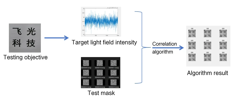


Visualization software operation interface. The software integrates a data acquisition card and DLP module drive control. Encoded image loading and projection can be performed through the GUI interface. The hardware triggers the data acquisition card to collect the light field intensity value and save it to disk. Reconstruction is performed by using the compressed sensing algorithm through Matlab.
| Categories | Specification and Model | Unit | Quantity |
| 6500 optical engine | Set including spatial light modulator F9120 DDR 0.65 1080P, base, and optical engine structure | set | 1 |
| Accessories for 6500 optical engine | Set including fixed base plate assembly and heat dissipation structure | set | 1 |
| Detector | Adjustable gain, 320-1100nm, bandwidth 11MHz, 75.4mm² | piece | 1 |
| Acquisition card | Set with 500Ksps 16-bit 16 RSE/NRSE channels or 8-channel DIFF analog input | set | 1 |
| Biconvex lens | Focal length 50mm, uncoated | piece | 1 |
| Sleeve | Length 50mm, with external slotting | piece | 1 |
| Bracket | Set including base plate, connecting rod, rod holder, fork block, rubber base, and M6 screws (several) | set | 1 |
| Tool | Breadboard handle | set | 1 |
Hardware-related advantages:
- The cost is relatively low: Compared with traditional high-resolution area array detector imaging systems (especially in some high-end detectors), the cost of single-pixel detectors combined with components such as spatial light modulators has advantages in some cases.
- Structural flexibility: The system structure can be designed to be relatively simple, compact and flexible, and it is easier to be arranged and applied in some scenarios with special structural requirements and space limitations.
- Relatively loose requirements for the detector: There is no need to rely on expensive and complex high-resolution two-dimensional pixel array detectors, and there can be more diverse choices when selecting detectors.
Advantages related to imaging performance and functions:
- Anti-interference ability: Regarding electromagnetic interference, etc., because only single-pixel detectors and simple optical paths are involved, it is not easily interfered by various electromagnetic environments. In some harsh environments, it can maintain stable operation more than the complex detector arrays in traditional imaging systems.
- Strong customizability: It can flexibly adapt to different imaging tasks and scenarios by changing the mode of the spatial light modulator and the characteristics of the active light source (such as intensity, frequency, modulation mode, etc.).
- Spectral adaptability: If the visible light band of the active light source is changed, imaging can be performed in different subdivided visible light bands, etc.
- Privacy protection potential: In some cases, if only obtaining general contour and other information of the scene (single-pixel imaging can achieve a certain degree of reconstructed images), it can better protect privacy and avoid excessive information exposure that may be caused by high-resolution images.
Other advantages:
- Scientific research value: It provides a new idea and approach for imaging technology, and helps to promote the cross-disciplinary research and development in the fields of optics, algorithms, materials, etc.
- Special scene application: In some special emergency scenes where traditional two-dimensional array imaging cannot be used (such as damage to some array detectors, etc.) but imaging is required, it can be used as an emergency imaging method.
