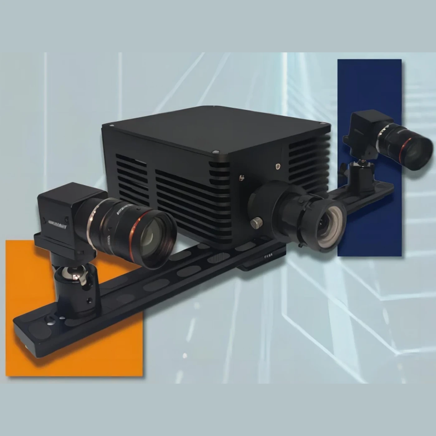
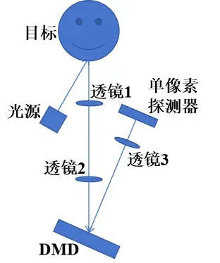
The passive short-wave infrared single-pixel imaging system is a technical system that uses the naturally existing short-wave infrared radiation in the environment, through special optical collection systems and light modulation methods, combined with single-pixel detectors and advanced algorithms, etc., to image the target scene.
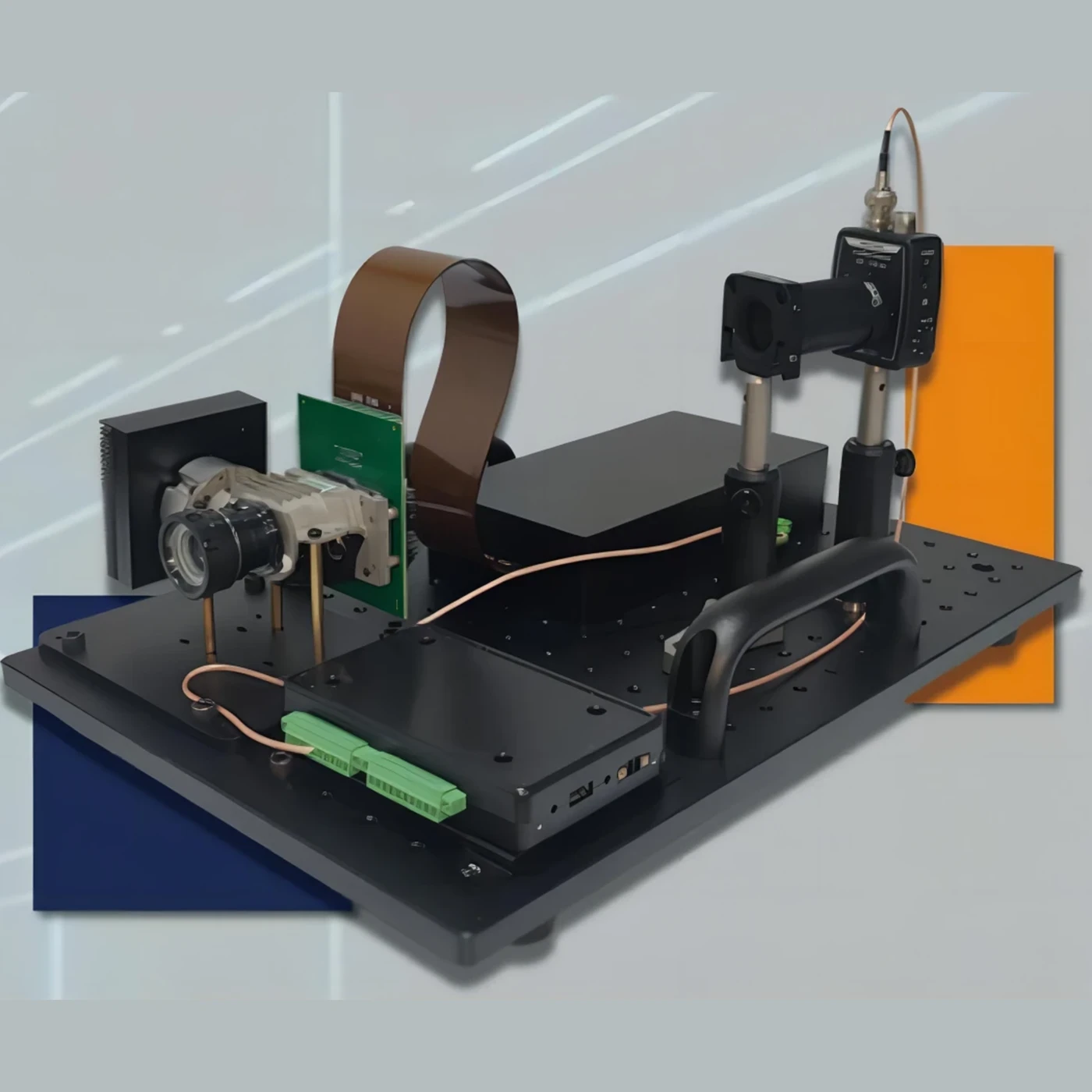
The passive single-pixel imaging system is mainly composed of an active illumination light source, three lenses with focal lengths of f1, f2, and f3 respectively, a digital
micromirror (DMD) spatial light modulator, and a single-pixel detector. As shown in Figure 1.
1、Calibrate the position of the active illumination light source to make the illumination light evenly cover the target.
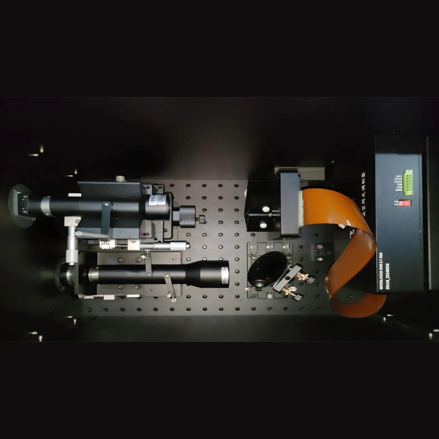
2、Establish the optical conjugate relationship between the target and the DMD through 4f imaging. The 4f imaging is achieved using two lenses with focal lengths of f1 and f2 respectively.
3、Load the preset random binary encoding on the DMD. The encoding switches over time sequence and calculate the ratio of the width of the projected image (x1) to the width of the detection surface of the single-pixel detector (x2).
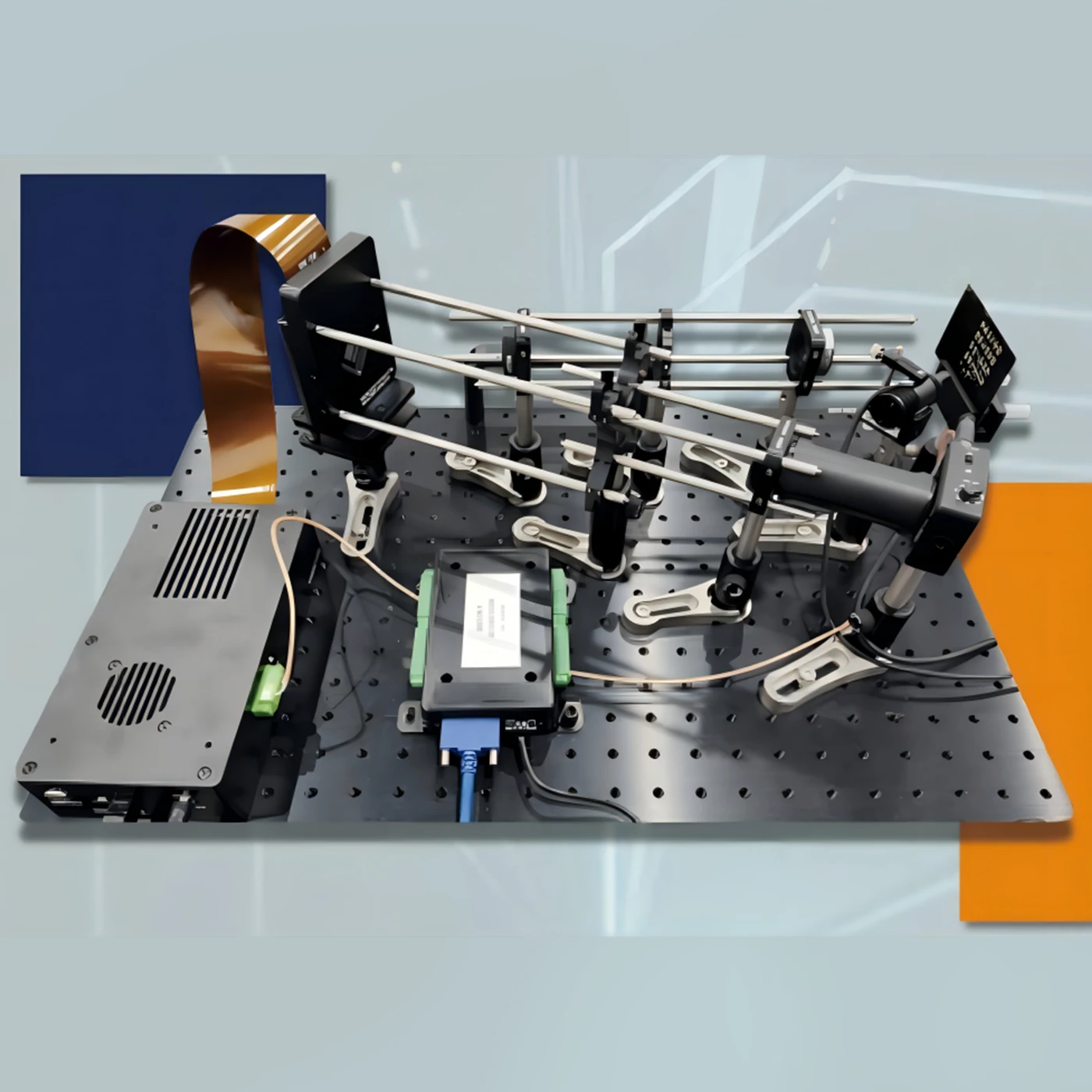
4、Realize the optical conjugate between the DMD and the single-pixel detector through single-lens imaging. Suppose the distance from the single lens to the DMD is L1 and the distance from the single lens to the detector is L2. L1 and L2 satisfy the single-lens imaging formula:
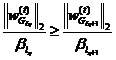
![]() , and at the same time should satisfy
, and at the same time should satisfy![]() . The center of the DMD, the center of the lens and the center of the single-pixel detector should be collinear. Among them, the single-pixel detector transmits the detection result to the computer through the acquisition card.
. The center of the DMD, the center of the lens and the center of the single-pixel detector should be collinear. Among them, the single-pixel detector transmits the detection result to the computer through the acquisition card.
5、The system realizes single-pixel imaging of a single target through multiple encoding and single-pixel acquisition methods. The number of encodings and the number of acquisitions are approximately 10% of the number of encoding pixels. The software algorithm obtains the target image by decoding the light intensity sequence collected by the single-pixel detector according to the encoded image.
The entire process mainly involves algorithms and techniques including the GAP-TV algorithm, random wavefront coding, etc.
GAP-TV algorithm:
The Generalized Alternating Projection (GAP) algorithm is a general reconstruction algorithm. GAP utilizes the Euclidean projections on two convex sets to enhance the data fidelity and the sparsity of the structure respectively. It does not require prior knowledge of the target scene and can effectively scale the size and compression ratio of the delayed image. In addition, as the algorithm proceeds, the results produced by the GAP algorithm monotonically converge to the true value. Monotonicity is generally observed in a wide range of experiments and is theoretically established under a set of sufficient conditions of the forward model. The reconstructed sub-frames are continuously improved in successive iterations. The user can stop the calculation at any time to obtain intermediate results, and the user can resume the calculation to continue improving the reconstruction. Figure 2 illustrates the basic principle of the GAP algorithm.
The following are the main steps of the GAP algorithm:
- Data fidelity is guaranteed by projecting
 onto a linear manifold composed of all eligible high-speed frames. This can be integrated into the observed snapshot g according to the forward model
 In other words,
 is the solution set of an undetermined linear equation system, which can be disambiguated by utilizing the structural sparsity of f in the transform domain.
- weighted value

Let ![]() ,
,![]() ,and
,and ![]() be orthogonal transformation matrices along two spatial coordinates and a time coordinate respectively. The frame f is represented in
be orthogonal transformation matrices along two spatial coordinates and a time coordinate respectively. The frame f is represented in ![]() as:
as:
![]()
The transform coefficients![]() are partitioned into m disjoint subsets
are partitioned into m disjoint subsets ![]() ,
,![]() , The weight of each group
, The weight of each group ![]() is a positive number
is a positive number ![]() , where
, where ![]() ,is a partitioning of the coefficient indices. When
,is a partitioning of the coefficient indices. When ![]() is a discrete cosine transform, the weights
is a discrete cosine transform, the weights ![]() , where
, where ![]() is a partitioning of the coefficient indices. When
is a partitioning of the coefficient indices. When ![]() is a discrete cosine transform, the weights
is a discrete cosine transform, the weights ![]() are chosen to emphasize low-frequency coefficients (and de-emphasize high-frequency coefficients); or when
are chosen to emphasize low-frequency coefficients (and de-emphasize high-frequency coefficients); or when ![]() is a wavelet transform, emphasize coarse-scale coefficients (and de-emphasize fine-scale coefficients).
is a wavelet transform, emphasize coarse-scale coefficients (and de-emphasize fine-scale coefficients).
A weighted value of size C, denoted as ![]() , is defined as
, is defined as ![]() where
where ![]() ,
,![]() is the standard
is the standard ![]() norm.
norm. ![]() is a subvector of w whose elements are indicated by the indices in
is a subvector of w whose elements are indicated by the indices in ![]() . Since structural sparsity is required not for voxels but for coefficients,
. Since structural sparsity is required not for voxels but for coefficients,![]() is the weighted value
is the weighted value![]() constructed in the space of transform coefficients
constructed in the space of transform coefficients ![]() . Due to the orthogonal transformations
. Due to the orthogonal transformations ![]() ,and
,and ![]() it rotates in the voxel space.
it rotates in the voxel space.
- Euclidean projection
The Euclidean projection of any ![]() onto
onto ![]() is defined by the following equation:
is defined by the following equation:
The Euclidean projection of any ![]() onto
onto ![]() is defined by the following equation:
is defined by the following equation:
![]()
where ![]() is the standard Euclidean norm. Only
is the standard Euclidean norm. Only ![]() for special values of C considered below are of interest.
for special values of C considered below are of interest.
- Alternating projections between Π and
 under systematic changes in C.
The GAP algorithm is a sequence of Euclidean projections between a linear manifold and a weighted ![]() that undergoes systematic changes in scale. Let the projection onto Π be denoted by
that undergoes systematic changes in scale. Let the projection onto Π be denoted by ![]() and the projection onto
and the projection onto ![]() be denoted by
be denoted by ![]() .
.
The GAP algorithm starts from ![]() (corresponding to
(corresponding to ![]() ) and iterates between the following two steps until
) and iterates between the following two steps until ![]() converges in t.
converges in t.
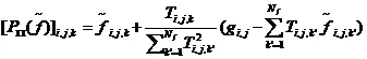
Projection on the linear manifold ![]() :
:
![]() ,
,![]()
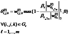
Projection on the weighted![]() :
:
![]() ,
,![]()
where,![]() denotes
denotes ![]() ,and is given by the following set of equations:
,and is given by the following set of equations:
![]() is an arrangement of
is an arrangement of ![]() in the following form:
in the following form:
Applicable to any ![]()
![]() dimension. It is not difficult to verify that the weighted size
dimension. It is not difficult to verify that the weighted size![]() used to derive the
used to derive the ![]()
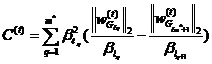
solution is represented by the following equation and depends on the latest prediction of ![]() :
:
GAP-TV replaces the constraint term of the weighted ![]() norm with the TV regularization term. While simplifying GAP, it achieves the approximate performance of GAP. TV mainly has the function of smoothing the interior of the target and non-smoothing at the edge of the target, making the reconstructed image smoother and eliminating artifacts. However, TV regularization is only verified for one type of video image in simulation comparisons and is evaluated only at a fixed compression ratio. For video compressive sensing with different sparsity and motion, a large number of experiments are still needed to further prove it. In addition, performing TV regularization only on two-dimensional images may lead to information loss or over-smoothing of the reconstructed image.
norm with the TV regularization term. While simplifying GAP, it achieves the approximate performance of GAP. TV mainly has the function of smoothing the interior of the target and non-smoothing at the edge of the target, making the reconstructed image smoother and eliminating artifacts. However, TV regularization is only verified for one type of video image in simulation comparisons and is evaluated only at a fixed compression ratio. For video compressive sensing with different sparsity and motion, a large number of experiments are still needed to further prove it. In addition, performing TV regularization only on two-dimensional images may lead to information loss or over-smoothing of the reconstructed image.
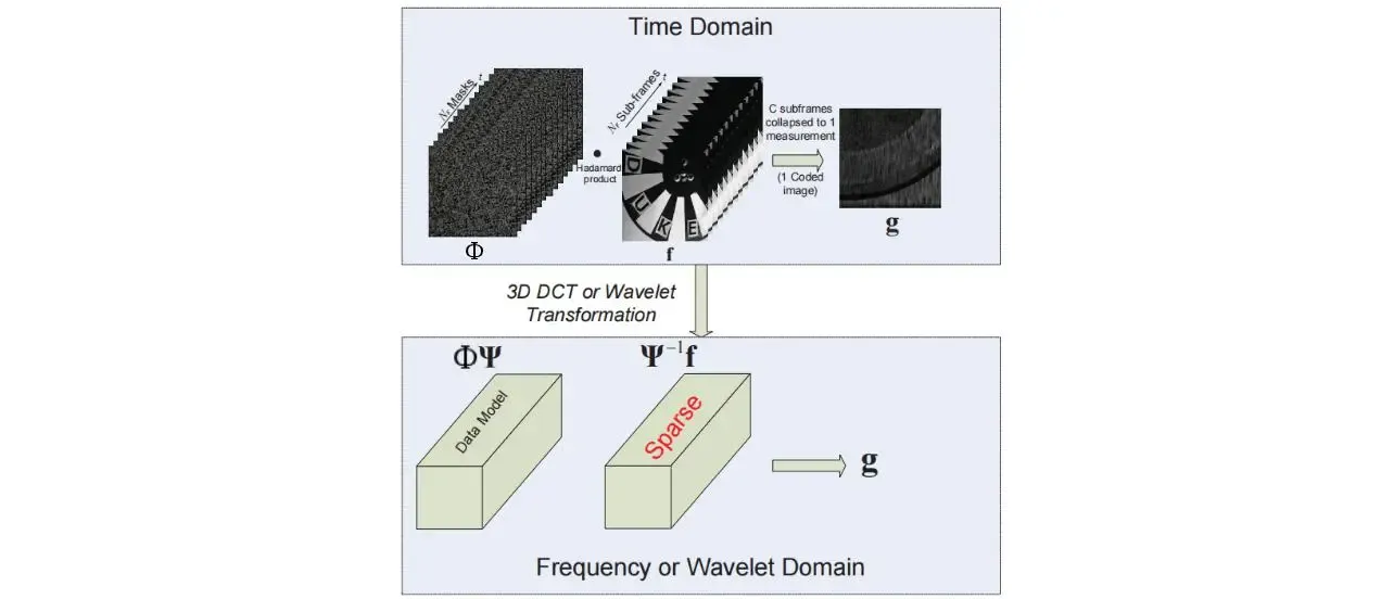
Single-pixel imaging compresses the two-dimensional spatial scene after encoding to the overall intensity value collected by the detector. The encoding is realized by the binary intensity modulation of the target reflected light by the digital micromirror array. This projection process can be described as the Hadamard product of the two-dimensional scene and the encoding. Under ideal conditions, the passive encoding of the reflected light of the two-dimensional scene by the DMD can be represented by the following mathematical process:
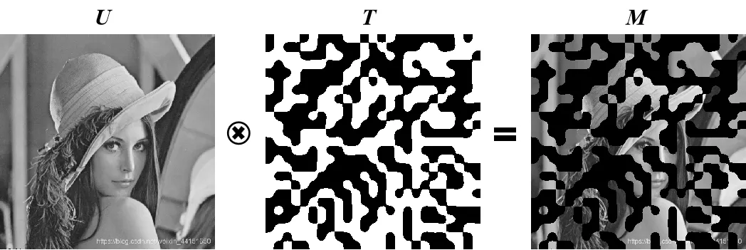
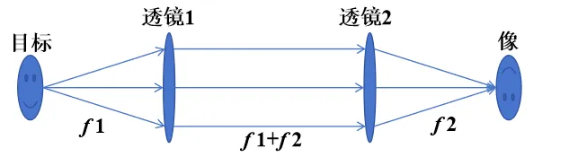
Among them, U is the reflected light field of the two-dimensional scene. It is projected onto the two-dimensional code T through 4f imaging, and the coded scene M is obtained by superposition. 4f imaging is achieved through two lenses. The working principle is shown in Figure 3.


Visualization software operation interface. The software integrates a data acquisition card and DLP module drive control. Encoded image loading and projection can be performed through the GUI interface. The hardware triggers the data acquisition card to collect the light field intensity value and save it to disk. Reconstruction is performed by using the compressed sensing algorithm through Matlab.
| Categories | Specification and Model | Unit | Quantity |
| DMD SLM | F4320 DDR 0.65 WXGA | set | 1 |
| Detector | 800 – 1800nm, adjustable gain with amplification | piece | 1 |
| Adjustable aperture | Diameter of light passage hole is 1 – 20.5mm, compatible with 30mm coaxial system | piece | 1 |
| Near-infrared light source | / | piece | 1 |
| Lens sleeve | Length 75mm with external slots | piece | 1 |
| Data acquisition card | 500Ksps 16-bit 16 RSE/NRSE channels or 8-channel DIFF analog input | piece | 1 |
| Bracket | Including base plate, connecting rod, rod holder, fork block, rubber base, coaxial vertical adapter plate, coaxial plate, L-shaped bracket, clamping piece, holder | set | 1 |
| Tool | Breadboard handle | set | 1 |
| Biconvex lens | f=50mm | piece | 1 |
| Biconvex lens | f=100mm | piece | 1 |
- 1.Low interference: It does not actively emit signals for illumination imaging. In some special scenarios (such as military reconnaissance, ecological monitoring, etc.), it can reduce interference to the target and the environment, and is not easy to expose its own existence and location.2.Low power consumption: Compared with active systems, it lacks high-power components such as transmitting light sources that work continuously. The overall power consumption of the system is relatively low, which is conducive to working for a long time relying on limited energy sources such as batteries or facilitating the energy supply of miniaturized devices.3.Safe and concealed: In some sensitive areas or fields with high requirements for security and confidentiality, the passive working mode can reduce the possibility of being discovered and monitored.4.Utilization of natural environmental light: It can utilize naturally existing starlight, moonlight, atmospheric glow, etc. as the source of the optical signal for imaging, and there is also a chance to image in low visible light environments such as at night.5.Relatively good penetration ability: The imaging ability under adverse atmospheric conditions such as smoke and haze is superior to that of visible light imaging. It can penetrate certain smoke, mist, etc., which is more favorable for the passive discovery of targets in scenes such as fire rescue and field search and rescue.
6.High sensitivity: It can detect relatively weak short-wave infrared radiation signals and can also sense weak signals in low-light environments.
7.Certain ability to identify camouflage: It can discover some targets camouflaged in visible light, such as being able to penetrate certain special camouflage materials, etc.
8、Relatively insensitive to temperature changes: Different from mid and long-wave infrared imaging which relies on the thermal radiation of the target, it is relatively less disturbed by the scene caused by temperature changes.
9.The system hardware is relatively simplified: Expensive and complex imaging sensors such as complex area detector arrays are not required, reducing the hardware cost, volume and weight, etc.
10.Flexibility: It is more flexible and deployable in some application scenarios where there are strict restrictions on the size and weight of the imaging system (such as space exploration, portable devices).
11.Simplification of data acquisition dimension: Since there is only one pixel detector for data collection, it is simpler and more efficient in data storage, transmission, etc. (at the raw data stage) than large-scale array data (although the subsequent data processing has certain complexity).