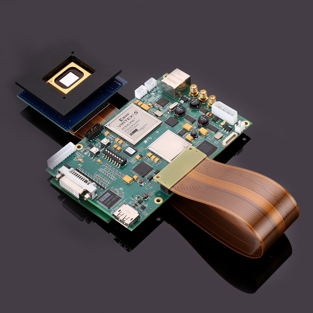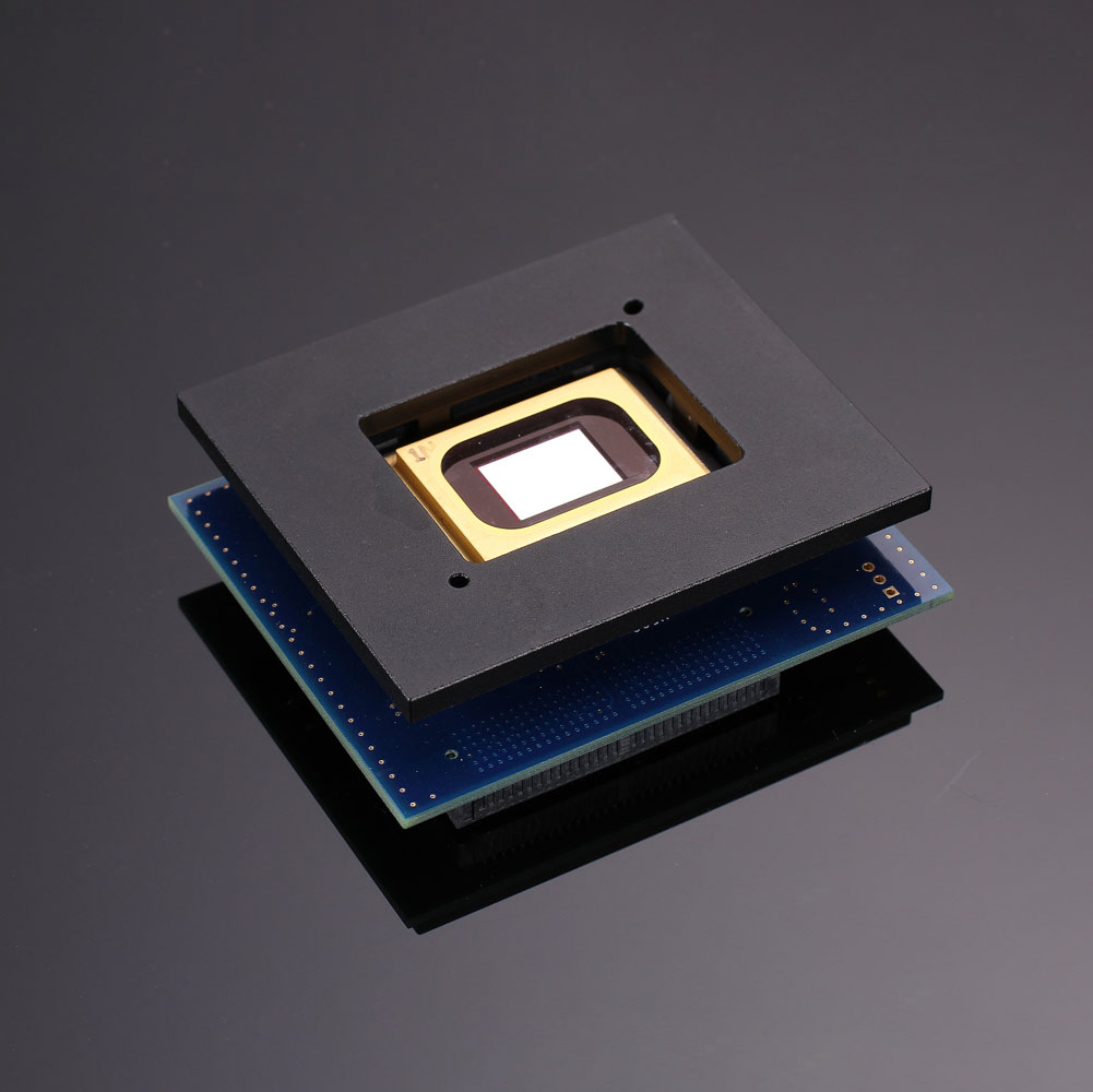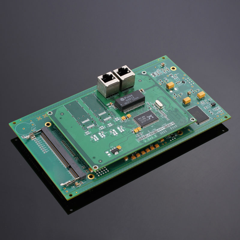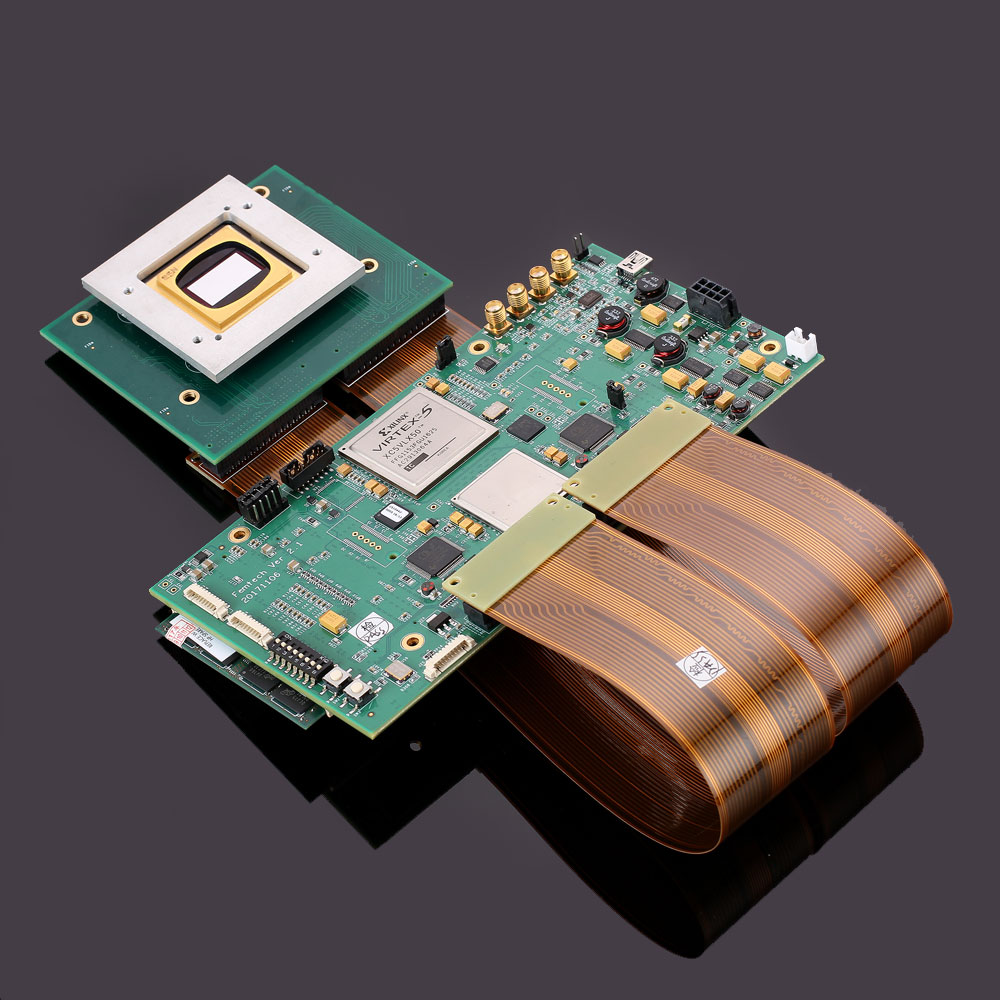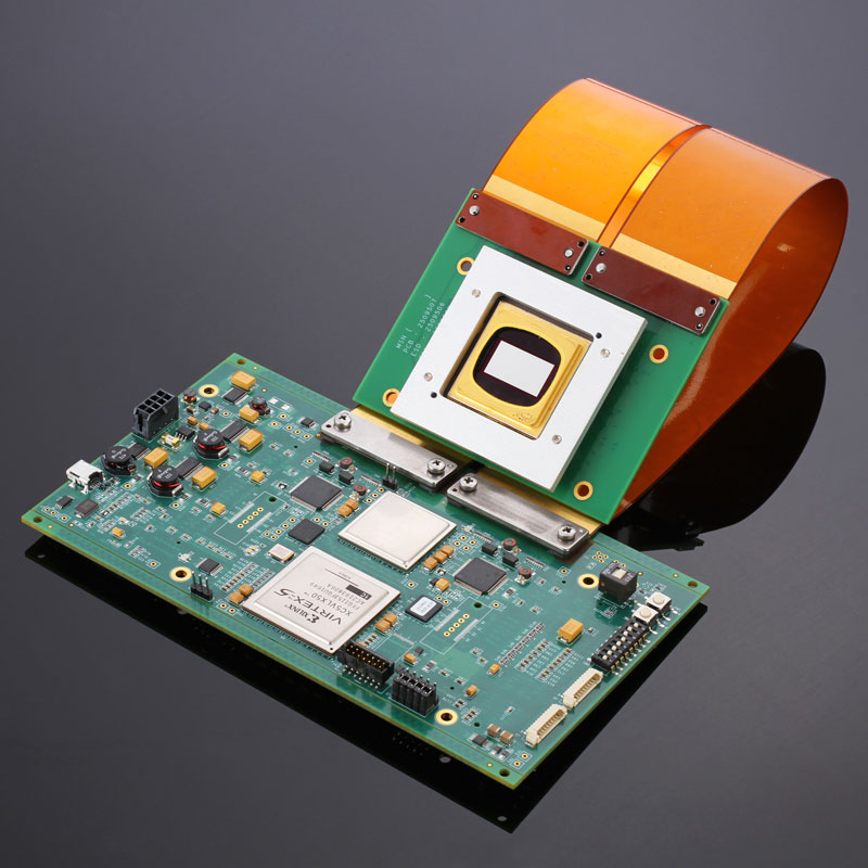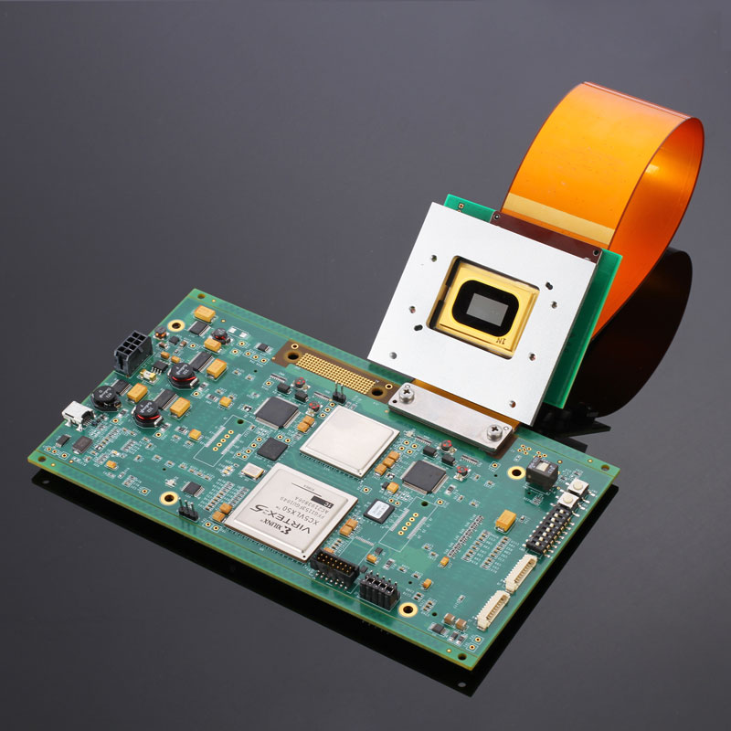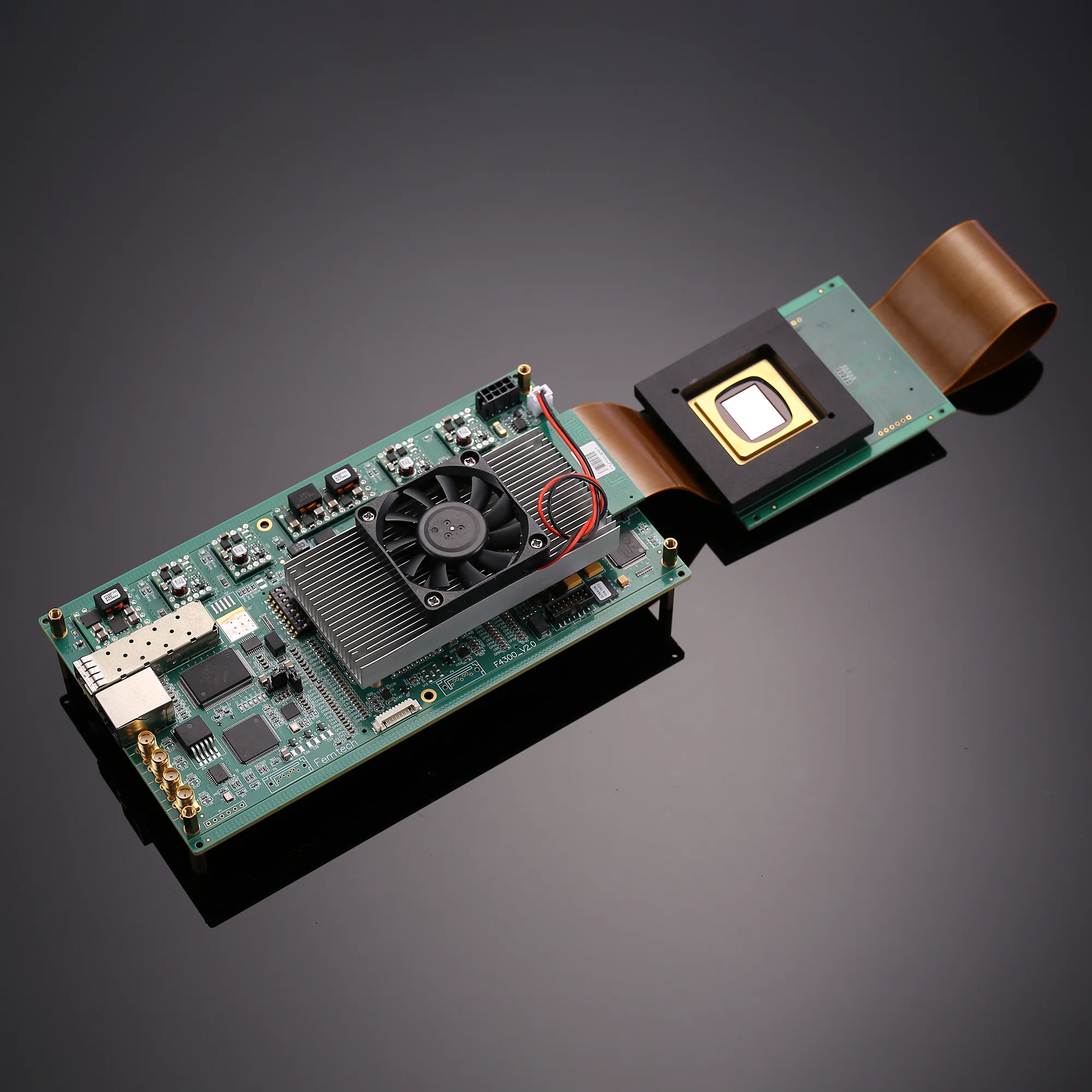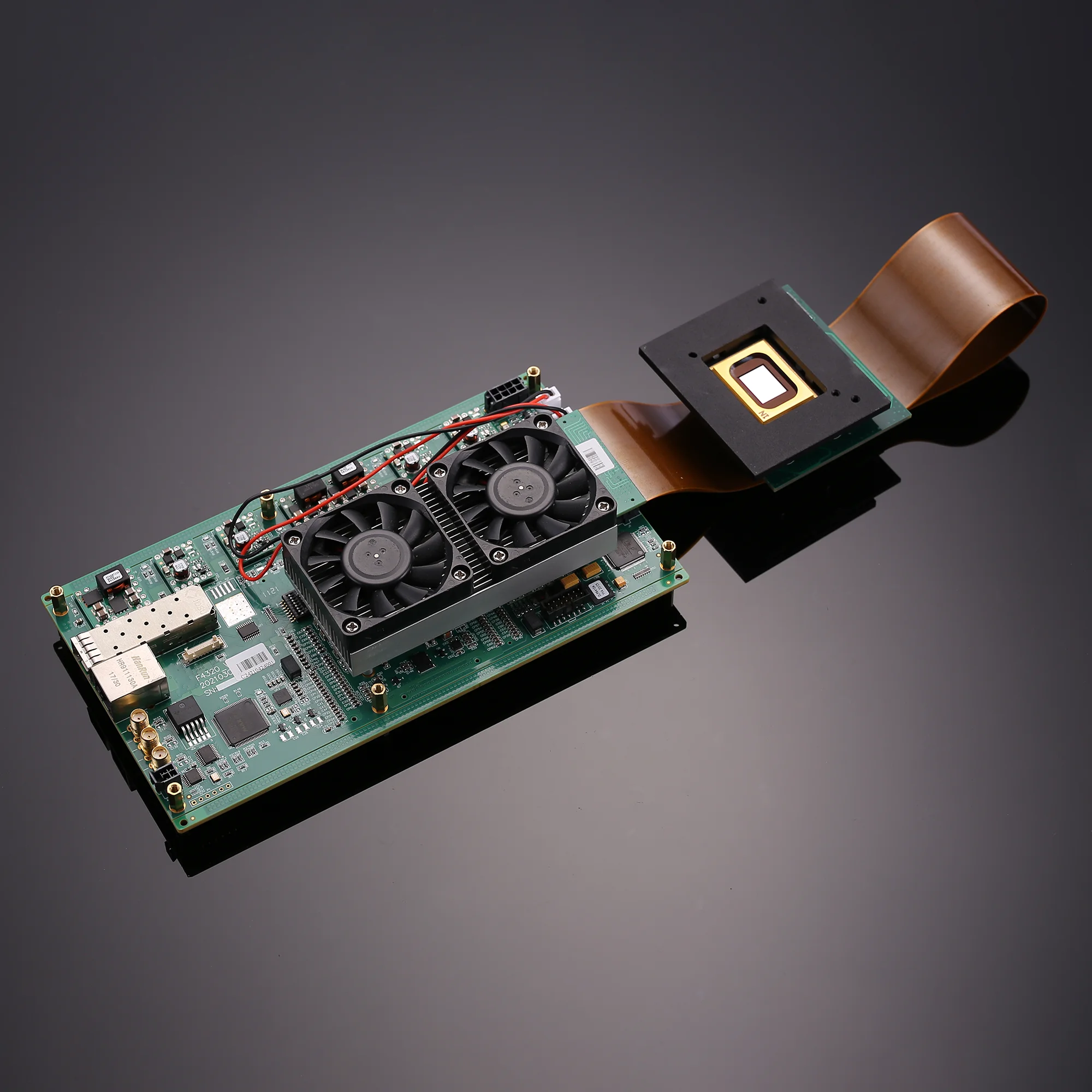
- Carry out optimization design on TI D4100 development system of Texas Instruments. DMD supporting 1024 X 768 resolution (with two micromirror structures, one is 13.68 microns with a diagonal length of 0.7 inches, and the other is 10.8 microns with a diagonal length of 0.55 inches);
- Support gigabit Ethernet high-speed transmission of pictures and control signals, with internal and external synchronization functions, and the synchronization pulse level standard is CMOS 3.3V; Support video DVI interface;
- The open control software is based on XP, Win7, and Win8 full speed drivers, and the program is written under VS2012. The open interface is conducive to secondary development;
- Support precise control of single micro mirror with XGA resolution; The micro mirror is locked at any time.
- Open FPGA architecture, providing secondary development options and customer customization functions for sample FPGAs;
- High speed binary and arbitrary grayscale image display; Contrast ratio: over 2000:1;
- Waveband: 350nm — 2700nm visible light;
| model | Sim4100 | |
| DMD | 0.55 XGA | 0.7 XGA |
| resolution ratio | 1024×768 | 1024×768 |
| Mirror element size | 10.8 µm | 13.68 µm |
| DMD band | VIS | VIS, UV, NIR |
| Clock frequency (maximum) | 400 MHz | 400 MHz |
| data bus | 32 LVDS pairs | 32 LVDS pairs |
| Data transfer rate | 25.6 Gb/s | 25.6 Gb/s |
| Maximum frame rate (Hz) | 32552 | 32552 |
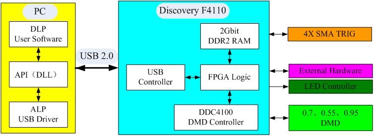
F4100 provides a common development platform. The platform consists of the following five parts:
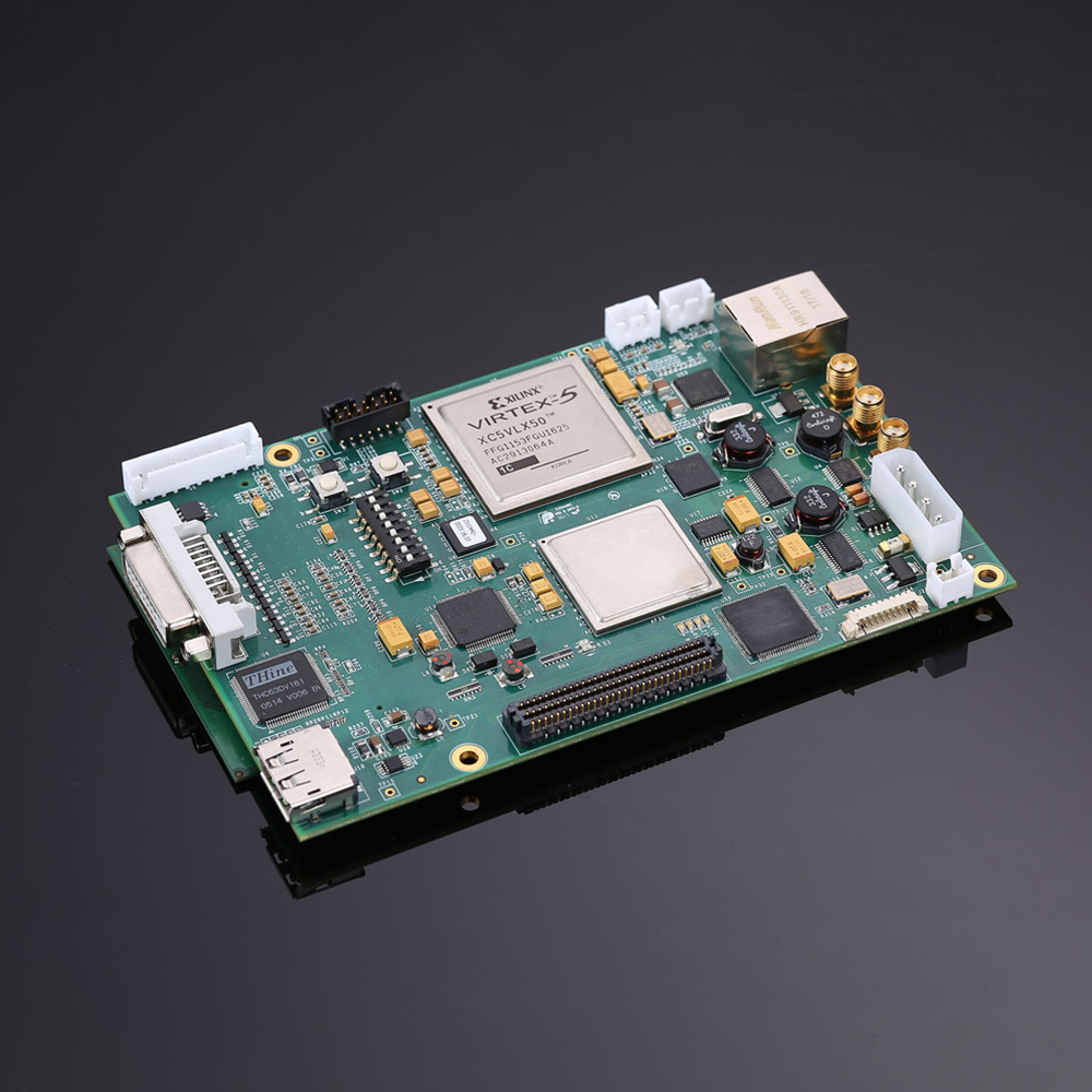
1. F4100 controller board;
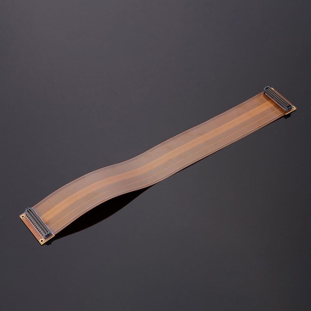
2. DMD motherboard, DMD chip, and cable;
3. Upper computer control software F4100 and D4100;
4. Power cable;
5. Experimental power supply, 5V @ 5A type.
The F4100 system provides complete interfaces (USB or extension interfaces), data processing (Virtex 5, DDR), and DMD controllers (DDC4100, DAD2000, DMD) in DLP development and application. The left diagram is a simplified schematic diagram of the F4100 control platform:
Sim4100 the development system includes::
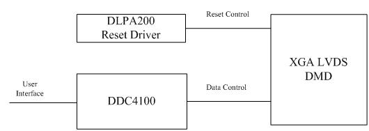
- 1. Power-on and reset driver for a single DAD2000: Realizing reset control for 16 blocks of the DMD mirror, while supporting higher frequency resets. The single DAD2000 operates in XGA mode;
- 2、DDC4100 digital controller: The FPGA XC5VLX30 chip from Xilinx Company is used to achieve complex control of DMD and DAD2000, providing high-speed 32bit/64bit Low Voltage Differential Signaling (LVDS) data and control user interfaces, all of which come from user FPGAs. Initialization and control of DMD and DAD2000 are implemented based on input signals from user FPGAs. The DDC4100 digital controller is actually an encrypted chip;
- 3、32bit/64bit, 400MHz double data rate (DDR) DDC4100 data interface: 32-bit XGA interface operation;
- 4、5V power input connector: on-board voltage regulator and other power supplies;
- 5、Large capacity user FPGA: FPGA XC5VLX50-1ff1153 for Xilinx company, for users to complete interface design and data processing;
- 6、A 64 bit DDR2 SODIMM connector: ultimately developing image storage for users;
- 7、Onboard Gigabit Ethernet controller: ultimately developing Gigabit Ethernet interfaces for users;
- 8、Output expansion connector: Connect to a standard compatible motherboard product. The board level design includes LVDS twisted pair design, supporting 32-bit LVDS connection to the expansion connector to achieve customer interface;
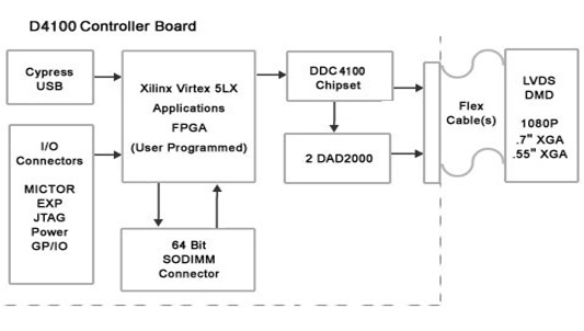
The simplified principle block diagram of DMD drive control is shown in the following figure:
- 3D measurement, 3D scanning
- Machine vision, machine placement
- Quality inspection, surface inspection
- Medical measurement, dental measurement
- Vascular imaging, biometrics
- Intelligent display, virtual reality
- Spectral analysis, chemical analysis
- Biological microscopy, microscopic imaging
- PCB exposure, 3D printing
- Scene generation, optical network, etc
| order number | Accessory Namequantity | quantity |
| 1 | DMD assembly module | 1 |
| 2 | SIM4100 control board | 1 |
| 3 | High speed display software | 1 |
| 4 | Power cable | 1 |
| 5 | Experimental power supply 5V@6A type | 1 |
| 6 | USB connection cable | 1 |
| 7 | Connecting the flat cable | 1 |
| 8 | Heat sink | 2 |
